
In Focus
Industry Issues
- Transition to Condition-Based Maintenance from Time-Based Maintenance
- Guidelines for Diagnostic Testing of Air-Operated Valves
- Temperature Spikes When Greasing?
- NMAC Crane Maintenance and Application Guide: 1000986 Update Project
- EPRI Transformer Guide—Copper Book Update
- Guidance for Developing an Electric Motor Specialist
- Transformer Paper Sampling
- Potential Impacts of Changes in Requirements for National Electrical Manufacturers Association Frame Motors
- Switchyard Equipment Maintenance Guide
- Improving Overall Transient Performance of Transformers
- Maintenance Management Guide—Vol. 1—Guidelines for the Maintenance Management of Plant Sensors
- NMAC Developing Motor Guide Web Application
- Developing an Effective As-Found Program
- Preventive Maintenance Program Guideline
- Tabular Listings of Equipment Failure Locations, Failure Mechanisms, Degradation Influences and the Maintenance and/or Condition-Monitoring Activities to Identify and Track Degradation Progression
- Safety and Relief Valve Testing and Maintenance Guide Rewrite and Upgrade
- Foreign Material Exclusion Wire Wheel Use and Alternative Products: The improper use of wire brushes will result in excessive loss of wire filaments
- EPRI Revising Condition-Based Maintenance Reports
- EPRI Publishes Generator Maintenance Guide for EDGs
- Comprehensive Reactor Coolant Pumps and Reactor Recirculation Pumps
- Control Rod Drive Hydraulic System Maintenance Guide
- Operator Rounds for Equipment Reliability
- The Impact of Maintenance Workload on Equipment Reliability
NMAC Meetings
- 2010 EPRI Hoisting, Rigging, and Crane Users Group Annual Meeting
- Rod Control Reliability Committee Working to Improve System Reliability
- Work Planning Managers/Supervisors Working to Improve Work Package Quality
- Circuit Breaker Users Group Update
- Mark Your Calendars for Upcoming Joint Emergency Diesel Generator Owners Group Meetings in 2012
- Japanese Reliability-Centered Maintenance–Condition-Based Maintenance Users Group Update
- Combined Condition-Based Maintenance Meeting
- Large Electric Motor Users Group Holds August 2010 Meeting
- Transformer Protection—Focus of 2010 Transformer and Switchyard Users Group Meeting
- Transformer and Switchyard Users Group Power Transformer Protection Workshop
- Emerson Hosts Diagnostic Workshop at Japanese Valve Users Group Meeting
- Pump Users Group Meeting
- Terry Turbine Users Group Meeting
- Mark Your Calendars for Upcoming Joint Emergency Diesel Generator Owners Group Meetings in 2012
- Pressure Relief Device Interest Group Update and Status
- 2011 NMAC Meetings
- NMAC Domestic Membership
- NMAC International Membership
- NMAC Personnel
In Focus
Improvement of Member Utilization of Maintenance and Equipment Reliability Products in Worker Practices
As outlined in the July NMAC Memo, we have begun an effort to assess how well NMAC products address the needs of maintenance personnel, specifically the maintenance technicians who work and maintain plant components, and to identify ways in which we can improve our product information and content.
Our initial scope and focus of investigation has been on products related to main feedwater system components. Our review of existing NMAC reports in this area has demonstrated areas where improvements can be made, not just in the specific products investigated, but also in the processes used to develop and prepare them.
The NMAC products that were reviewed as part of this effort are identified in Table 1.
Table 1: The NMAC products that were reviewed as part of the investigation into products related to main feedwater system components
| Subject Area | NMAC Product | Report Number |
|---|---|---|
| Main Feedwater feedwater Pumpspumps | Main Feedwater Pump Maintenance Guide | TR-105933 |
| Mechanical Seal Maintenance and Application | 1000987 | |
| Shaft Alignment Guide | TR-112449 | |
| Nuclear Maintenance Applications Center: Large Flange and Casing LeakagLarge Flange and Casing Leakage | 1013466 | |
| Lube Oil System Leakage Mitigation | TR-111413 | |
| PM Templatetemplate | ||
| Main feedwater pump motors | Electric Motor Predictive and Preventive Maintenance Guide | NP-7502 |
| Electric Motor Tiered Maintenance Program | 1003095 | |
| PM Templatetemplate | ||
| Main feedwater pump turbines | Feedwater Pump Turbine Controls and Oil System Maintenance Guide Feedwater Pump Turbine Controls and Oils Systems | 1003094 |
| Main feedwater system air- operated valves | Nuclear Maintenance Applications Center: Air-Operated Valve Maintenance Guide: Revision 2 Air-Operated Valve Maintenance Guide | 1016682 |
| Valve Positioner Principles and Maintenance Guide | 1003091 | |
| PM Templatetemplate |
Although some of the products provide information that is important and useful for maintenance worker practices, some appear to be lacking in guidance and recommendations that would have enhanced or improved the quality of activity being performed. NMAC products often contain a large amount of information, including component descriptions, failure mechanisms and a troubleshooting guide, condition-monitoring recommendations, preventive maintenance tasks, and maintenance practices.
As part of the study, NMAC has requested and received examples from our members of sample maintenance instructions/procedures so that their content can be benchmarked to the content of the products. Although our products cannot practically be written in the format used by our members, they should contain detail and critical information needed to ensure that effective steps have been identified. The structure of the NMAC report format lends itself to this important aspect, with the use of Key Points to identify key steps; however, additional improvements in the methodology are being planned and will be implemented. These actions will be identified in future NMAC Memos.
Part of the investigation is to study the integration of existing skill verification modules in the Plant Support Engineering (PSE) Standardized Task Evaluation (STE) program. This program is an activity that develops testing modules that are used by participating organizations to assess craft skills for various functions. One conclusion that has resulted from this review of the STE information and how it is developed is that NMAC should become involved in the STE module development in the future. Often, a technical advisory group (TAG) is formed for a component level guide; this collection of expertise could be also chartered with identifying the important skills needed by maintenance personnel while at the same time developing and including in the maintenance guide those critical steps that should be performed during routine maintenance activities, such as assembly, disassembly, installation, setup, and alignment.
Going forward, we have already begun to make changes to our methodology and processes for development and preparation of future products. These changes will be implemented on all future efforts. We are currently looking at ways to back fit and incorporate this approach to previously issued products. Given the volume of information that is available, a structured approach will be needed to go back and assess past products, identify gaps, and plan for corrective measures as appropriate.
Through EPRI's participation in various industry events and organizations, it is clear that worker knowledge and practices, which are key to reliable plant operations, are a continuing challenge for members. Contributing factors are aging workforce, personnel turnover, and outsourcing of staff support. There are a number of industry initiatives along these lines, and we will continue to be involved and play an integral part of the solution for our members.
If you would like to find out more about this project or to participate in this effort as a member of the TAG, contact Mike Pugh, 919.812.5162, mpugh@epri.com.
Update to NMAC Freeze Sealing Guide
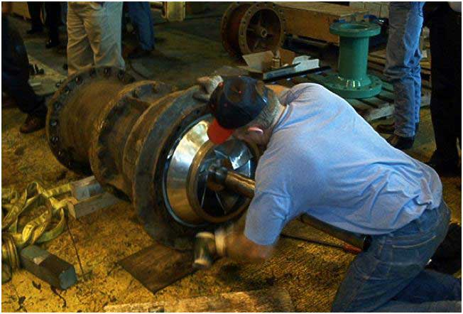
The EPRI report Freeze Sealing (Ice Plugging) of Piping, Revision 1 (TR-016384-R1) was issued in 1997. Events have occurred since that time that require an update to the report. The desire to limit impact on outages and on-line activities often includes the consideration of freeze sealing as a method for isolation of equipment for maintenance.
The report covers the considerations for using freeze sealing so that an informed decision to use this method can be made. Considerations for performing the operation, such as metallurgical properties of the piping, methods of cooling, and industrial safety practices, are covered to help technical personnel evaluating the operation, maintenance supervision, and work planners and procedure writers can provide guidance so that workers to ensure a safe and effective freeze seal.
This update to the report is incorporating operational experience since the last report update and addressing specific issues found to be of concern to members. Figure 1 shows a typical freeze fixture for piping.
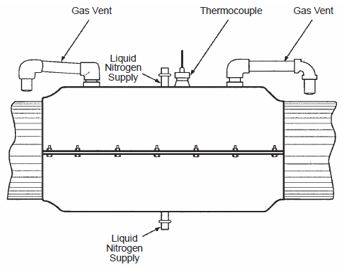
Figure 1. A typical freeze fixture for piping using liquid nitrogen
An important technical issue that is being researched in this report is the concern by some utilities concerning martensitic transformation in austenitic stainless steels. Resolution of this concern appears to be on the horizon. A technical advisory group (TAG) of utility members and vendors from the United States and abroad has been formed. The TAG has yet to formally meet because of numerous utility and vendor conflicts. Based on this, the update will not be published until 2011.
In addition to the update of this report, EPRI will consider the development of a hands-on technical workshop covering planning, supervision, and performance of freeze seals in accordance with this new guideline, based on direction from the TAG.
For more information on the update to Freeze Sealing (Ice Plugging) of Piping, Revision 1, contact Gary Boles, 704.595.2781, gboles@epri.com.
Update to NMAC On-Line Leak Sealing Guide
The report On-Line Leak Sealing: A Guide for Nuclear Power Plant Maintenance Personnel (NP-6523-D) was issued in 1989. Events have occurred either while performing the on-line leak sealing operations themselves or in preparation for the task that have necessitated an update to the report. Figure 1 shows a peripheral sealing fixture with an injector for a pipe flange. Figure 2 shows a leak seal fixture with a shutoff adapter and strongback.
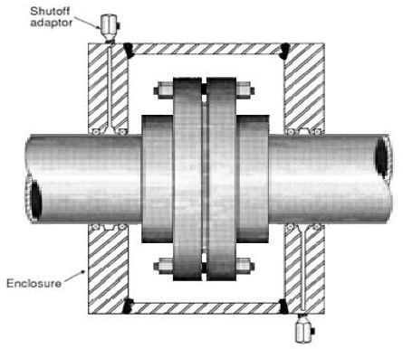
Figure 1. A peripheral sealing fixture with an injector for a pipe flange
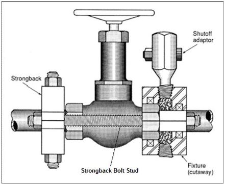
Figure 2. A leak seal fixture with a shutoff adapter and strongback
The report will reflect new techniques for performing on-line leak sealing and lessons learned that have generally been adopted by leak sealing companies to address problems that have occurred with the success of various techniques. The report is generally intended for engineering personnel who are evaluating the suitability of on-line leak sealing techniques and reviewing information provided by leak sealing contractors and for the leak sealing contractors themselves. Use of the report provides consistent expectations and guidance for utility and vendor personnel.
Because on-line leak sealing is generally not performed by utility personnel, a technical advisory group (TAG) of U.S. and international members has been formed and the report is nearing completion. The group held a productive meeting in August 2010. The report is nearly ready for final TAG review and should be issued in early 2011.
Many techniques have been changed over the years to significantly reduce the risk of injection of sealing compound into the fluid stream. Cautions to utility personnel and vendors involving the possibility of intergranular stress corrosion cracking (IGSCC) when carbon steel fasteners are involved in fluid leakage will be a major caution of the report because a near-miss accident recently occurred at a U.S. plant when valve bonnet bolting failed unexpectedly during leak sealing preparation activities. It was found that many personnel do not associate IGSCC with carbon steel components because it is usually thought of as a phenomenon occurring only in stainless steels commonly used in nuclear power plants.
For more information on the update to On-line Leak Sealing: A Guide for Nuclear Power Plant Maintenance Personnel, contact Gary Boles, 704.595.2781, gboles@epri.com.
Update to the NMAC Outage Guide
A major focus of the industry is improvement in the execution of refueling outages. For example, the Utilities Service Alliance has made this a major focus area for the plants in the alliance. Plants in the United States have experienced an increase in events causing loss of key safety functions, such as shutdown cooling. In addition, many plants are not meeting target schedules for outages. Outage durations are increasing for many plants even ignoring the long outages needed for such large projects as steam generator replacements, reactor vessel head replacements, or extended power uprates. Industry oversight groups have made this a focus area and are strengthening the high-level guidance in this area.
Many international plants currently use a highly regulated and relatively short refueling cycle (for example, 12–14 months) in which much time-based maintenance and inspection is part of the regulatory strategy. They now wish to move to the approach used in the United States in which longer fuel cycles (18–24 months) are common and work scope is based on actual equipment condition and not just time-based maintenance even if the equipment appears to be trouble-free.
The aging work force leaves many utilities with expertise in planning and executing outages short of the experience needed at a time when utilities might have failed to capture the best practices used to execute effective outages that met target schedules. Many new or inexperienced outage managers need a place to go for best practice information.
The update to Effective Refueling Outage Preparation and Execution Guidance (1014480) will provide best practice guidance to the industry to address these issues. Gaps in the outage process, such as consideration of nuclear safety risk and defense in depth, were not addressed in the 2007 report.
A technical advisory group has been formed with 10 utility members, a representative from the Institute of Nuclear Power Operations, and EPRI expertise. Other consultants may be used as needed. So far, participation by the industry has been excellent. The first face-to-face meeting is scheduled for December 13–15, 2010. It is anticipated that another face-to-face technical advisory group (TAG) meeting will be needed in June or July 2011. Issuance of the report is expected late in the third quarter of 2011. A workshop to roll out the results of the report to the industry is anticipated in December 2011 or January 2012 pending TAG input. Figure 1 provides one utility's graphic view of the outage planning process.
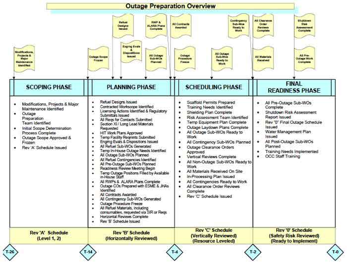
Figure 1. An overview of outage preparation
Industry personnel interested in learning more about this effort or participating in a TAG or case studies for this effort should contact Gary Boles, 704.595.2781, gboles@epri.com.
NMAC Pump Resource Web Page Now Available
 |
A new web-based resource is now available to EPRI Nuclear members that will enable members to navigate to the various NMAC products on power plant maintenance and troubleshooting and provides other resources, such as an industry pump database, pump repair specifications, pump program description and self-assessment aids, and other information. The pump resource is located at the following link: http://membercenter.epri.com/programs/065755/Pages/Unique%20Pages/PumpResource.aspx
 |
Features include drop-down menus, search features, and other common methods to help members quickly locate resources. Access will continue to be controlled through established EPRI membership controls. You will need to log on with your EPRI ID and password if you are not connected when you go there.
Right now, the link is not available on the existing EPRI web platform (or the current NMAC or Pump Users Group [PUG] pages), but that will be changing in the near future as www.epri.com is rolled out. (At that point, this pump link should be available on those sites as well.) But members can add this link to their favorites and access the page as needed.
In the future, this new web page will be maintained and updated by the NMAC PUG as new technology and information emerge.
Member Value
The purpose of this new format is to provide easy access to and to serve as a road map to member personnel on existing NMAC products and resources that will enable them to better maintain and troubleshoot problems with power plant pumps. The report will help educate and quickly familiarize new and existing personnel on what information is available for maintaining power plant pumps.
For more about this new web-based product, contact Mike Pugh, 919.812.5162, mpugh@epri.com.
Industry Issues
Transition to Condition-Based Maintenance from Time-Based Maintenance
Most utilities agree that they are expending resources on some maintenance tasks with little gain in equipment reliability. Utilities have provided input to NMAC that they underuse a condition-based maintenance (CBM) strategy for some equipment. With this strategy, degradation of equipment is monitored using various methods and maintenance is performed on a planned basis before failure occurs.
The report Transition to Condition-Based Maintenance from Time-Based Maintenance will focus on the following:
- Why some plants underuse CBM
- When to choose CBM as a primary strategy for some equipment
- What prerequisites, such as management support, programmatic support, hardware, culture, risk awareness, and integration of such strategy into the work management processes, should be in place to implement CBM
- How to implement CBM
- The need for further research to allow the use of CBM where it may not be practical because of technology limitations
The report is intended for use by maintenance management, maintenance engineering, system engineering, component engineering, predictive maintenance, and work management personnel. By using the report, utilities will be able to determine which areas they need to work on to establish or strengthen their CBM program, whether the need is for management support or establishment of predictive maintenance implementation.
A technical advisory group (TAG) meeting was held in September 2010 with five utility members and several EPRI support staff. The TAG established the outline for the report, identified opportunities for benchmarking within the nuclear industry and outside the industry, and discussed reasons for less than adequate implementation, as well as what has worked well at some plants.
Probably, the most notable realization in the TAG meeting is that the Preventive Maintenance Database (PMDB) that EPRI sponsors (often called PM Templates) is often thought of as a list of tasks–all of which should be performed to prevent failures. In fact, the PMDB establishes a comprehensive list of all available tasks to address failures. In addition, the PMDB provides the effectiveness of these tasks to address degradation so that personnel can select the tasks that can be practically performed and understand the effect on reliability of performing (or not performing) those tasks. With that knowledge in hand, tasks that address exactly the same degradation might be eliminated because the incremental improvement in performance diminishes as more tasks are performed that address the same degradation. In addition, if the most effective tasks are nonintrusive in nature, the equipment would be a candidate for CBM as its primary strategy. Training of key personnel to use the tool may be part of the solution to provide a basis to stop performing tasks that are providing little improvement in performance.
The writing of the report has begun, and the report should be available for members in late 2011.
Industry personnel interested in learning more about this effort or participating in a TAG or case studies for this effort should contact Gary Boles, 423.870.5979, gboles@epri.com.
Guidelines for Diagnostic Testing of Air-Operated Valves
The use of diagnostic testing has become an essential element in many plants' air-operated valve (AOV) programs. Diagnostics can be used to verify that AOVs are capable of performing their design function, calculating as-left margin, trending valve performance, and troubleshooting. Many AOVs are diagnostic-tested in accordance with the plant's preventive maintenance (PM) templates. A properly maintained and calibrated valve will perform at optimal levels and improve efficiency and cost effectiveness.
NMAC recently initiated a project to develop a report that will provide guidance on performing successful valve diagnostic tests for maintenance and engineering staff at power plants. It is believed by both NMAC and the Air-Operated Valve Users Group (AUG) that the number of AOV failures can be reduced by better using diagnostics. Understanding the valve condition prior to maintenance can go a long way in ensuring that appropriate maintenance tasks are completed as needed, thereby strengthening the overall PM program.
Key topics for the report to include are the following:
- Common diagnostic tests and the information that can be extracted from the tests
- Optimal test setup and test conditions, including the following:
- Sensor styles (for example, ETT, QSS, C-clamp and pressure)
- Correct sensor placement
- Test durations
- On-line versus off-line testing
- Sensor styles (for example, ETT, QSS, C-clamp and pressure)
- Test frequencies
- Guidance on how often a valve should be tested
- Prioritization of testing
- Regulatory requirements as they relate to diagnostics
- Guidance on how often a valve should be tested
- Case histories, including a discussion of trace analysis with practical examples
A kick-off teleconference was held at the end of August to discuss report content. A first draft should be available first quarter 2011.
If you would like to become part of this effort or learn more about the report content, contact Nick Camilli, 704.595.2594, ncamilli@epri.com.
Temperature Spikes When Greasing?
Did you know that it is not uncommon to experience bearing temperature increases with the addition of grease? The results from our test stand indicated that a temperature spike of 25°F (-3.9°C) after greasing is not uncommon. This was just one of the key findings from the research performed for the EPRI report Nuclear Maintenance Applications Center: Effective Grease Practices (1020247), which was published in 2010.
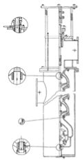
An experiment was conducted using a pillow block test stand with double-shielded pillow block bearings and an automatic lubricator with a 4-in. (101.6-mm) line to the bearing. The housing was connected to a 1/3 horsepower motor by a jaw-type coupling and mounted on a stand, as shown in Figure 1.
The motor was operated for a given amount of time until the temperature of the bearing stabilized. For this experiment, the temperature leveled out at approximately 135°F (57.2°C). As grease was added to the bearing, there were quick temperature spikes that indicated when grease was added by the autolubricator. This is best depicted in Figure 2 on the bottom race of the pillow block bearing. Over the course of 90 minutes, grease was added at various intervals, as indicated by the orange triangles on the graph. There is a steady temperature increase seen as the grease is consistently added to the bearing. The temperature levels off at about 160°F (71°C) and then starts to gradually come back down as the bearing is purged. This repeatable cycle confirmed the condition of viscous churning, where the temporary increase in grease quantity present in the worked area of the rotating elements results in a temperature rise resulting from fluid friction in the grease.
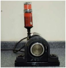
Figure 1. A spherical pillow block bearing test stand with an autolubricator
Figure 2. The temperature profile of the top and bottom of the outer race on the pillow block bearing (A correlation can be seen between the spikes in temperature and the times when grease is added.)
So how does one apply this knowledge to practical applications? Even though this experiment applies to only a single type and configuration of pillow block bearings, it does provide valuable insight into periodic relubrication of bearings and the impact on temperature levels. This is important to a comprehensive maintenance program where infrared thermography or periodic contact temperature measurements are made on bearings. Normal relubrication can result in the temperature spikes such as those seen in this experiment, and if the temperature measurement is made of these bearings within hours of relubrication, it might give a false indication of concern if the grease-churning effect is not understood. If a relubrication event has recently occurred and a higher-than-baseline temperature is seen, trending to observe the plateau and return to normal or leaving and then coming back to check after several hours or another shift might be the correct course of action for determining action points based on bearing temperature measurement.
These tests also showed a strong correlation between temperature spikes and ultrasonic readings while initiating grease to a pillow block bearing. To learn more about this phenomenon and other effective grease practices, download report 1020247.
For more information, contact Nick Camilli, 704.595.2594, ncamilli@epri.com.
NMAC Crane Maintenance and Application Guide: 1000986 Update Project
The EPRI report Crane Maintenance and Application Guide: Maintenance and Application of Overhead Cranes (Containment, Fuel Handling, Turbine Building, and Intake Structure) (1000986) was published in 2000. Since that time, industry practices regarding the use and maintenance of overhead cranes have evolved, crane-related regulations have been updated, and some overhead cranes have begun to exhibit age-related reliability issues. Additionally, there has been 10 years of related industry operating experience (OE) that needs to be reviewed with lessons learned incorporated into the updated guideline as required.
The specific objectives of this project are as follows:
- Review the current practices related to the use, inspection, and maintenance of overhead cranes within the nuclear industry, and update the report as required. * The review will include updating the report to reflect all applicable changes in regulations impacting the operation, inspection, and/or maintenance of overhead cranes.
- Include, where applicable, information related to long-term overhead crane reliability, aging, and other current industry issues such as the following:
- Degraded equipment (structures and crane components)
- Obsolete parts
- Variable frequency drives
- Degraded equipment (structures and crane components)
- Inspection methodology to reduce outage time for critical cranes (for example, polar cranes), such as the following:
- Upgrading crane options, methodology, and concerns (including single failure proof)
- Crane health tracking methodology
- Oversight of vendor/contractor crane maintenance
- Crane health tracking methodology
- Upgrading crane options, methodology, and concerns (including single failure proof)
- Conduct a review of all overhead crane-related OE since the original publication date of 2000. Potential sources of OE data include the following:
- Institute of Nuclear Power Operations OE database
- World Association of Nuclear Operations OE
- Nuclear Regulatory Commission
- Internal site OE supplied by individual technical advisory group (TAG) members
- Institute of Nuclear Power Operations OE database
The first TAG meeting for the project was held in Shreveport, Louisiana, after the completion of the Hoisting, Rigging, Crane Users Group meeting in late June 2010. The next TAG meeting was scheduled for November 16 and 17, 2010, at the EPRI office in Charlotte North Carolina. The purpose of this TAG meeting is to conduct a final technical review of the updated report prior to preparing it for publication. It is anticipated that the completed report will be available to the industry on January 31, 2011.
For more information, contact Lee Catalfomo, 813.996.3357, lcatalfo@epri.com.
EPRI Transformer Guide—Copper Book Update
Work on the Copper Book for 2010 will include updates to Section 1 (Transformer Fundamentals) and two additional sections: Operations (Section 7) and Monitoring and Diagnostics (Section 9). Originally, Monitoring and Diagnostics was going to be Section 8, but for the sake of order and logic, it was decided to make Maintenance Section 8 and move Monitoring and Diagnostics to Section 9.
In conjunction with the 2010 EPRI Transformer and Switchyard Users Group (TSUG) meeting, the Power Transformer Working Group provided a limited review of the content of the 2010 chapters being added to the Copper Book.
It is essential that the industry provide review and input to this resource book. The Copper Book is a comprehensive report that captures the current industry guidance for the application and maintenance of power transformers in the electric power industry. The name of the book represents a series of reports developed by the EPRI Power Delivery and Utilization Group that uses a color book series for various major equipment areas. The development of the Cooper Book is being sponsored by multiple programs, and sectors within EPRI—nuclear, power delivery, and generation—are combining efforts in funding and expertise in the development of this project.
As of 2010, there will be six sections of the Copper Book completed with about six more to be done by the time the project is completed. The plan in 2011 is to complete three sections—Section 5 (Factory Testing and Inspections), Section 6 (Shipping and Installation), and Section 11 (Asset Management). The task to cover all things transformer is truly an effort to capture the best information available for the application and maintenance of power transformers. To capture the best information, it is essential to have input from all quarters—including users, manufacturers, industry experts, and other organizations.
There is limited time to provide comment for the 2010 sections. Feel free to review any of the sections, but it would be much better to get involved during the development of the sections.
If you are interested in participating in the development of the Copper Book, contact Wayne Johnson, 704.595.2551, wejohnson@epri.com.
Guidance for Developing an Electric Motor Specialist
This EPRI report provides a guideline for the development of a person who will specialize in the plant usage of motors. The skill sets are presented so that each site can determine which skills it would want its motor specialist to develop and at what pace. The knowledge and skills identified in this report are based on issues encountered by EPRI Large Electric Motor Users Group (LEMUG) members through their years of plant experience in the motor area. The specific topics and areas covered in the report reflect input from industry support groups and equipment suppliers.
Electric motors have received increased attention at nuclear power plants in recent years. Many large horsepower, medium-voltage motors have been in operation since plant startup using the original insulation system. Some are starting to show signs of aging and are requiring increased maintenance attention, including insulation system replacement. The failure of a critical motor can be detrimental to the operation and safety of a nuclear power plant. Also, the industry has entered an era of plant life extension for many current operating plants. Although most plants have solicited for a 20-year life extension, some have plans to operate an additional 20 years.
In order to meet the challenge of continued reliable operation, large horsepower electric motors will be critical to that reliable operation. Just as these concerns for life extension and reliable operation were becoming more obvious, the Institute of Nuclear Power Operations (INPO) issued three topical reports on large pump motors that identified increased impact on power plant performance because of motor failures. The reports highlighted the need to develop improved motor program features to reduce future failures and the impacts of failures. The three topical reports are Analysis of Large Pump Motor Failures Impacting Power Production (TR4-35), Review of Events Impacting Power Production Involving Large Pump Motors (Supersedes Topical Report TR4-35) (TR5-50), and Review of Events Impacting Large Pump Motors (TR7-59). These three topical reports emphasized increased utility activity and involvement with their motors, including predictive and preventive maintenance, being aware of equipment aging, performance trending, plant personnel training, vendor oversight, and the need for critical spares.
As a follow-up document, INPO published an Engineering Program Guide (EPG-13) for motors. This document provided guidance for the nuclear sites on what should be contained within a motor program and the respective motor program owner's responsibilities. Many of the EPRI motor reports developed through the LEMUG, a key forum for motor industry support and participation, are listed within EPG-13.
The findings of these reports and especially the requirement for plant personnel training increased the need for industry involvement in activities surrounding electric motors. The INPO reports have also led to the emergence of the need for more robust site motor programs and for someone to be responsible for the maintenance of these programs—a motor specialist or component specialist.
The report provides skill sets using a tiered approach that could be used by anyone responsible for motors to develop the knowledge and skills to become a motor specialist. The report is being developed by identifying specific topics and areas that have been encountered by EPRI LEMUG members through years of supporting plant operations. The skill sets contain specific learning topics, references, formal training opportunities, recommended observations, and suggested hands-on or eyewitness participation.
The report is divided into four skills sets, each with the expected motor-specific knowledge, basic plant knowledge, tasks knowledge, and a degree of industrial involvement in motor-related issues. Each skill set will include potential training options and references to information sources to support the skill set topics. Time references may be attached to each skill set to allow the future motor specialist to gauge career development progress, but time is not the critical item—knowledge is.
Numerous utilities and vendors supplied input to this report through their participation in the LEMUG Information Working Group meetings. The training, knowledge, and skills recommended are provided based upon past experiences of the participants.
For additional information, contact Wayne Johnson, 704.595.2551, wejohnson@epri.com.
Transformer Paper Sampling
The majority of transformers in the power industry are used in the transmission and distribution of electricity. However, it is generator step-up (GSU) transformers that allow the power generated by power plants to be placed on the transmission system.
Transformer insulation is universally made of the time- proven combination of cellulose paper and pressboard, fully impregnated with insulating oil. When the insulation is overstressed by high temperature or electrical discharges, the chemical bonds within oil and cellulose molecules can be broken. The life of a liquid-filled transformer is based on the condition of the bulk insulation, which consists of the winding insulation, separators, and oil.
Over the past decade, standards organizations have been very active in evaluating the topic of insulation life and how it is affected by time and temperature. Loading guides have been written and techniques have been developed to evaluate the life of insulation systems. However, attempting to answer these questions over the years has been very difficult because the loads on most transformers vary considerably throughout the day and according to the season. Actual loading records are also rare, making any life analysis difficult for the average large transformer.
In order to obtain data from transformers that have stable loading, this project will look at GSU transformers that have been used at nuclear power stations. Typically, GSU transformers at nuclear power stations have very high load factors, constantly applied, and they are monitored very well. Commercial nuclear power dates back more than 30 years. Many stations are replacing transformers now, and many have planned replacements for the next few years. The transformer replacements at nuclear power plants offer an extraordinary opportunity to analyze these well-documented installations to help answer many of the questions concerning the effect of loading on transformer insulation life.
This project will collect data from these units and attempt to correlate the effectiveness of condition assessment tools, such as dissolved gas analysis, furan concentration, and moisture content to the thermal age of the transformer, as determined by measuring the degree of polymerization of the actual winding insulation.
If your site is planning a transformer replacement, before the unit is scrapped, this project would like to obtain oil and paper samples from the hot spot area of the transformer to aid in the data collection for this project.
Contact Wayne Johnson, 704.595.2551, wejohnson@epri.com, to discuss obtaining paper samples from your scrapped transformer.
Potential Impacts of Changes in Requirements for National Electrical Manufacturers Association Frame Motors
 |
|
| Used with permission from Baldor. Courtesy of National Electrical Manufacturers Association |
EPRI recently published Nuclear Maintenance Applications Center: Recommended Practice for Evaluating Interchangeability for NEMA Frame Motor Replacement (1021428). This report was written to highlight legislative mandates that could impact the use of standard-sized electrical motors in power plant applications.
The National Electrical Manufacturers Association (NEMA) T-frame motor may be the most highly standardized equipment in the power plant. NEMA has maintained the same design standards for approximately 45 years for motor mounting dimensions, torques, and other design parameters.
Several pieces of legislation have impacted the energy efficiency requirements for NEMA T-frame motors. The 1992 Energy Policy Act (EPAct) became effective October 24, 1997. This law mandated certain general-purpose industrial motors with ratings up to 200 horsepower (149 kW) sold in the United States meet the nominal full-load efficiency values provided in NEMA publication MG-1, Table 12-11.
The 2005 EPAct required that government agencies procure electric motors that would meet the efficiency standards of NEMA MG 1 (2006) Table 12-12 (NEMA Premium1 Efficiency Levels). These requirements were only applicable to motors between 1 and 200 hp (0.75 and 149 kW).
The Energy Independence and Security Act (EISA) of 2007 requires that NEMA general purpose motors from 1 to 200 hp (0.75 to 149 kW) sold in the U.S. meet the efficiency requirements of the 2005 EPAct (NEMA Premium Efficiency Levels). The EISA extends the energy efficiency requirements to include NEMA motors used in certain industry and commercial applications that were not preciously covered by the 1992 EPAct. Another significant part of the EISA is that it further requires NEMA motors rated from 201 to 500 hp (150 to 373 kW) to meet the efficiency standards of the 1992 EPAct.
The changes in motor efficiency requirements resulting from EPActs directly affects commercial, safety-related non-environmentally qualified (EQ) and safety-related EQ NEMA frame motors. The unique attributes associated with safety-related and EQ motors had to be addressed; however, differences of opinion arose within nuclear power plants as to whether a design change package was necessary when replacing a NEMA motor rated at 600V or below with a motor of the same size and rating. There was a need for sufficient technical justification and guidance for equivalency evaluations to allow EPAct motors to be used in place of pre-EPAct motor designs.
Although there are many physical and performance attributes that require a comparison evaluation, it is expected that most EPAct T-frame NEMA motors rated at 600V or below will not require a design change for installation. The safety-related non-EQ and safety-related EQ motors will require more engineering input to ensure that they meet quality assurance and EQ requirements in addition to the physical and performance attributes.
EPRI 1021248 provides guidance for replacing an older NEMA T-frame motor with a new energy efficient T-frame motor. Guidance was sought from motor manufacturers on interpreting motor nameplate information and performance curves. Input from operating power plants was solicited on what, in their opinion, should constitute a change of such significance to require a design change analysis. The report recommends that key data for old and new motors be recorded in a Configuration Control Motor Change-Out Record Document. This document standardizes the information that should be evaluated to accommodate EPAct electric motor installations.
When the decisions were made to require more energy efficient motors, the potential effects on power plant systems were not a primary consideration. The issues that led to some plants' concerns as to whether a design change would have to be undertaken were a result of the potential difference in performance characteristics, weight, and length of EPAct motors versus original plant equipment. The report provides guidance on equivalency evaluation of the critical differences between the original plant equipment and EPAct motors and the technical basis of why they can be used. Use of this report can help determine whether design changes would be needed for EPAct motors when replacing original non-EPAct plant motors.
EPRI 1021248 was developed because of the issues addressed by the EPRI Large Electric Motor Users Group. The Applications Working Group was primarily responsible for the development of this report.
For additional information, contact Wayne Johnson, 704.595.2551, wejohnson@epri.com.
1. NEMA Premium is a registered trademark of the National Electrical Manufacturers Association.
Switchyard Equipment Maintenance Guide
Because of various issues in the industry, power-generating stations have become responsible for reliability of some switchyard equipment. Deregulation in the power industry has caused a separation between companies that generate power and those that deliver power to the customer. Along with deregulation, 10CFR50.65 (Maintenance Rule) and Institute of Nuclear Power Operations (INPO) AP913 have required nuclear power plants to focus on equipment that will maintain plant and component reliability. Additionally, in the 2005 Energy Policy Act, the North American Electric Reliability Corporation was named the electric reliability organization, which gives it the power to truly regulate the delivery of electricity. This organization has developed a standard that requires plants to develop a report that defines the interface and responsibilities between the generator operator and the associated transmission entities.
EPRI will be looking at the equipment that most power plants will either be directly responsible for or use outside organizations to maintain. Even if the equipment belongs to another company, the generating station must be aware of the impact that the other equipment can have on continued plant operation.
In general, in substations there is a site on which is located the major circuit bus and equipment as well as a control house. The control house contains protection, control, metering, and communication equipment as well as equipment related to the ancillary power systems (station service, 125vdc, and so forth).
The typical switchyard or substation contains the following components:
- Bus
- Outdoor equipment including the following:
- Switching
- Power transformers
- Instrument transformers
- Reactive power compensation
- Lightning and surge protection
- Grounding grid
- Conduit and/or trench
- Lighting, power distribution, and communications
- Support structures
Because different companies and organizations have different operating and maintenance philosophies, it is important that agreements be in place for equipment and/or activities that affect the connection points between these organizations. For instance, the main or generator step-up transformer is the key device that allows a generating station to connect to the grid. However, depending on the design of a plant, there can be various ways in which isolation between the transformer and grid and the transformer and the generator has to be accomplished. There could be circuit breakers, a disconnect switch (manual or motor-operated), or removable links. All of these connections are methods that can be used to disconnect the plant from the grid on the plant's side.
Because operating experience (OE) is limited for switchyard equipment, it is anticipated that significant surveying and equipment history has to be collected for review and evaluation. The goal of the project is to collect industry knowledge and lessons learned from the OE related to various pieces of switchyard equipment, such as the following:
- Disconnect switches
- Potential transformers
- Current transformers
- Lightning/surge protectors
- Insulators
- Others
The goal is to better understand the design, performance, and maintenance required for this equipment in order to meet plant and company reliability goals. Because plant personnel have not had responsibility for switchyard equipment in the past nor have transmission companies had to collect operating data, this will be a great opportunity for each group to exchange information in order to meet mutual equipment reliability goals.
The Switchyard Equipment Working Group, which is part of the EPRI Transformer and Switchyard Users Group, will be the technical advisory group for this task.
For additional information, contact Wayne Johnson, 704.595.2551, wejohnson@epri.com.
Improving Overall Transient Performance of Transformers
The issue of improving main power transformer transient performance was discussed during an R&D gap analysis process that was conducted to review transformer guidance provided by EPRI and available from other sources in the industry.
Understanding the types of transients, capturing the data, and determining what effects transients may have on transformer performance and life are some of the items to be covered by this project.
There is a need for a broader understanding of the methods and means to protect transformers from transients (switching events and lightning strikes). Current practices provide for protection of main power transformers through various types of protective devices, such as surge and lightning arresters. Several failures have occurred in power transformers that have been attributed to lightning strikes, the opening of circuit breakers, and other system transients. Because transformer failures have been attributed to transients, enhanced surge protection (for example, surge arrester locations) was considered for research, and techniques for improved testing of protective devices were clear needs in the industry.
In order to determine which transients are affecting transformers, a review of existing data for typical power system transients should be conducted. After determining the transient data, the methods used to detect and record transients that affect transformers should be reviewed to ensure that what is being reported as transient effects is truly attributable to transients. There has to be some discussion to determine whether there needs to be improved transformer design (that is, more resilient designs) to make transformers more transient-resistant or better ways to protect the transformer from exposure to transients and/or ways to minimize transformer exposure to transients.
In order to accomplish these tasks, methods of capturing and evaluating the effects of through faults on transformers are essential. Transformers cannot be protected from all faults. But if fault exposure can be limited, areas where improved protection should be provided and properly implemented can be identified.
The material should cover typical transformers, such as generator step-up, unit auxiliary, and startup, and other emergency transformers essential for operating a typical power plant. These transformers are typically liquid-filled and supply power to operate power plant auxiliary systems.
For additional information on this project, contact Wayne Johnson, 704.595.2551, wejohnson@epri.com.
Maintenance Management Guide—Vol. 1—Guidelines for the Maintenance Management of Plant Sensors
This report (1021429) presents general knowledge about the principal sensors found in nuclear power plants. It provides basic information on sensor operation. Furthermore, it provides discussions of problems that may be encountered when performing testing and recommends strategies for maintenance of these sensors. This report should assist seasoned instrumentation and control engineers or technicians when troubleshooting nuclear plant sensor problems. The report will be useful when formulating maintenance plans.
Plant life extension has placed considerable pressure on operating plants to maintain plant systems to improve plant availability and prevent unscheduled plant shutdowns. Plant sensors are the first step in acquiring plant data for safe and continued operations; therefore, a thorough understanding of their use, testing, and operation is essential to increased plant reliability.
Continued safe plant operation relies on the sensor technologies that measure or monitor plant processes. However, few, if any, efforts have been undertaken in the past three decades to develop new sensor technologies in support of extended plant operation. Until recently, manufacturers have had little reason to invest in new products for a stagnant market having very high expectations and extensive testing and qualification requirements, such as the nuclear power industry. In fact, even the developments that have been made in the last few years have been adaptations of digital interfaces for older, trusted sensor designs. Most of these developments were not for the nuclear industry but were to satisfy the demand from other markets eager to adopt anything digital. Some manufacturers have continued to produce replacements for some sensors, and others have ceased production because of decreased demand. Therefore, with no new sensor developments in the foreseeable future, dwindling inventories of currently used sensors, obsolescence issues for those that are in use, and few choices for replacements, the industry is faced with meeting the challenges of continued operation using the sensors that are available today.
In order to support continued safe operation, effective methods for handling the aging and obsolescence of sensors and other plant equipment must be implemented now in operating plants. To effectively continue to use sensors based on conventional sensing technologies, the plant system engineers and/or technical staff must have a thorough understanding of the conventional technology. For example, safety-related temperature measurements are still done with resistance temperature detectors and thermocouples that have been around for more than a century. Pressure measurements (including differential pressure measurement for determining level and flow) are still measured using conventional capacitance cells, bellows, bourdon tubes, and strain gauge technologies.
This report assembles the accumulated knowledge about the most important sensors found in nuclear power plants. It defines what they are, describes how they work, suggests procedures and processes for evaluating their condition, outlines the signs of sensor failure based on industry knowledge, and then formulates the management practices for monitoring and testing these important components throughout their lifecycle.
This report is the first of two volumes that will address maintenance management of plant instrumentation and control components. The information found here is a unique compilation of information essential to the understanding of the operation and function of pressure, temperature, flow, nuclear, and ultrasonic sensors.
For additional information and to participate in the completion of this project, contact Wayne Johnson, 704.595.2551, wejohnson@epri.com.
NMAC Developing Motor Guide Web Application
The comprehensive motor guide project is a complement and follow-up to the comprehensive pump guide that is being developed by NMAC. The concept for the report is to provide EPRI members with a web-based application that will assist members of varying knowledge levels to identify the information for their specific need from the voluminous amount of available EPRI material on motors and their subcomponents through an interactive web page format. Access to this information will be through www.epri.com.
Work on this report started in spring 2010, and we plan to complete it in spring 2011. The concept of a web-based application was introduced at the January 2010 Large Electric Motor Users Group (LEMUG) meeting in the Information Working Group breakout session by Jerry Honeycutt. A demonstration of the pump comprehensive web application by Mike Pugh of NMAC was provided. Because the pump web application was started last year and has been mostly developed, we are going to leverage the lessons learned by Mike Pugh and the EPRI Information Technology (IT) group working on that effort and apply them to this project. For those reasons, we have been delaying our effort while the pump web application has been in development.
To date, we have had one technical advisory group (TAG) meeting in July 2010 in Dallas. At that meeting, the concept and scope of the comprehensive motor guide were discussed, using the pump web application beta site as an example. The content was brainstormed, and a layout was discussed. We created basic storyboards of our concept for a sample flow from the entry page to the information source page. This concept was presented by Jerry Honeycutt at the September 2010 LEMUG meeting, and feedback was obtained.
Moving forward, the project team had a web meeting with the EPRI IT personnel on October 12. The basic layout and storyboard concept was presented in order to obtain confirmation that our ideas could be developed into a web application from the IT perspective. Access rights for EPRI reports and use of links to other information sources (such as National Electrical Manufacturers Association, Institute of Electrical and Electronics Engineers, and American Society of Mechanical Engineers) were also discussed. We received positive feedback that our concept is compatible with the new www.epri.com capabilities and that we should move forward with development of storyboards.
The next TAG meeting was scheduled for November 2 and 3 in Charlotte. Al brainstoring session was planned to finalize the overall scope of the site content and our proposed web page layout and information flow. The resultant information will be developed by Jerry Honeycutt into storyboards for each information path. We plan to have a project update Web meeting with the TAG on January 12 to discuss progress and raise any issues. Then, we plan to provide the status and possibly present these storyboards at the Information Working Group session during the January 2011 LEMUG meeting.
Based on the feedback from the January LEMUG meeting, we will move toward turning over the storyboards to EPRI IT for creating the initial web application. TAG members will be asked to test, review, and comment on the web application and subsequent updates. Additionally, TAG members will be asked to supply the information, images, drawings, and so forth that are required to enhance the web page layouts. Subsequent meetings will be held through webcasts or possibly one additional face-to-face meeting in the first quarter of 2011 to support the spring 2011 web page rollout.
For additional information, contact Drew Mantey, 484.467.5864, amantey@epri.com.
Developing an Effective As-Found Program
In today's power production industry, only a small fraction of the useful information obtained while performing preventive maintenance (PM) activities is actually recorded. The information that is recorded is very often in the form of brief and nondescriptive entries provided by maintenance personnel in PM work orders. Another activity is the operational interface through operator rounds and data collection that is vital to equipment reliability. In most cases, the only feedback information is in the form of a corrective action, when something is identified as a problem. Operational information is being acquired by operations, on a regular basis, in the form of data sheets and electronic data entry. In most cases the obtained information, whether in the form of hard copy or electronic, is reviewed, signed off on, and filed away, never reaching the individual who is responsible for the equipment reliability. The capture and review of the actual as-found equipment conditions (while performing a specific task) by responsible individuals is a vital step in implementing a living PM program. It is this information and the associated determination as to the extent of degradation or conditions that can directly influence future PM task activities and intervals. This information plays an important role in a living PM program, while improving equipment reliability and availability and reducing maintenance costs.
For this information to be best used, it should be placed in an electronic format that can be trended to alert the responsible individual to abnormal conditions and/or developing problems.
This project will describe and develop the tools necessary to capture, convert, and trend as-found information that can be used to better determine the actual equipment operational conditions. This information can then be used in the evaluation process to continuously improve the living PM program and assist with providing solid justifications to make changes to existing PM activities.
This project will provide value in the following manner:
- Provides a better understanding of component conditions
- Provides the tools necessary to capture, convert, and trend as-found information
- Provides a tool to monitor maintenance effectiveness
- Provides a means to manage component degradation
- Bolsters the living PM program continuous improvement process
The project will be accomplished in three phases. The first phase is to produce a draft report by the end of 2011 and begin the development of a tool that can be used for an effective as-found program. This will be accomplished by the following:
- Contract a technical writer to develop report documents: February 2011
- Assemble a technical advisory group (TAG): February 2011
- Hold a TAG meeting to identify tools for the capture, conversion, and trending of information that can be used for developing and implementing an effective process for documenting as-found component status: March 2011
- Contract a software consultant: April 2011
- Issue the first draft report to TAG members: May 2011
- Hold a TAG meeting to review the first draft report and begin developing an as-found program tool: June 2011
- Issue the second draft report to TAG members: August 2011
- Hold a TAG meeting to review the second draft report: September 2011
- Develop a prototype of an as-found program tool: September 2011
- Issue the third draft report to TAG members: November 2011
- Hold a TAG meeting to review the third draft report: December 2011
The second phase will produce a published report and testing of a prototype tool for an as-found program. This will be accomplished by the following:
- Secure member prototype testing of an as-found program tool: January 2012
- Begin testing the as-found program prototype tool: February 2012
- Hold a TAG meeting to review test results: June 2012
- Incorporate comments and prepare the final draft report: July 2012
- Issue the final draft report to TAG for review: August 2012
- Hold TAG meeting to review final draft report: September 2012
- Submit final draft report to publishing: October 2012
- Publish Developing an Effective as-Found Program report: December 2012
The third phase will produce an effective as-found program tool. This will be accomplished by the following:
- Develop an as-found program tool: January 2013
- Test the as-found program tool: May 2013
- Roll out the as-found program tool for member use: July 2013
Members will have the ability to better understand as-found information and make informed decisions when adjustments are required to their existing living PM program, helping to ensure the continued reliability and availability of plant assets.
For additional information, contact Jim McKee, 704.595.2777, jmckee@epri.com.
Preventive Maintenance Program Guideline
Over the years, EPRI has developed many reports for the industry to aid with developing effective maintenance (preventive, predictive, and condition-monitoring) programs to ensure equipment reliability and availability. The industry has drawn on this information to establish preventive maintenance (PM) programs or enhance existing programs. However, in some cases not all PM program processes have been implemented and some programs subsequently have been left marginally effective and vulnerable to failure. A PM program is designed to be a living program, meaning that it should change along with plant work processes and plant modifications and continuously improve. If the program is rigid and/or becomes stagnant, it will leave equipment vulnerable to failure.
Like plants, the industry's engineering and maintenance work force is aging and being replaced with young, less-experienced personnel. Their knowledge and awareness of EPRI technical information regarding the implementation of a living PM program need to be addressed.
To make all this relevant research readily available to the membership, the information needs to be compiled into one reference source that contains all attributes of a living PM program.
This report will be accomplished in the following manner:
- Identify all of the attributes of a living PM program and how they relate
- Identify and review existing EPRI reports, identifying reports that may be candidates for updating and revision
- Compile the living PM program information into one report, referencing existing information as necessary
- Develop a living PM program flowchart
This project will provide an effective means for the members to evaluate the structure of their existing PM programs to ensure that they have the necessary elements to implement and continuously improve an effective living PM program. It will accomplish the following:
- It will provide the end user with a single point of reference.
- The information can be applied to all member plants.
- The application of this product will identify the most effective activities that should be in place to ensure continued equipment reliability, thereby reducing equipment failures, which typically result in immediate and widespread costly repairs and a loss of generation.
The project will be accomplished in two phases. The first phase is to produce a draft report by the end of 2010. This will be accomplished by the following:
- Contract a technical writer to develop technical report documents: complete
- Assemble a technical advisory group (TAG): complete
- Hold a TAG meeting to identify key program elements, EPRI reports, and so forth to formulate the basis for a living PM program: complete
- Issue the first draft for TAG review and comments: December 2010
The second phase will produce a published technical report. This will be accomplished by the following:
- Hold a TAG meeting to review the draft report: January 2011
- Issue the second draft for TAG review and comments: March 2011
- Conduct teleconference TAG meeting(s) to review the second draft: April 2011
- Issue the final draft report to the TAG for review: May 2011
- Hold a TAG meeting to review the final draft report: July 2011
- Submit the final draft report to publishing: September 2011
The results of this project will provide an effective means for the members to assess their existing PM programs to ensure that they have an effective living PM program implemented. This will accomplish the following:
- It will provide the end user with a single point of reference.
- The information can be applied to all member plants.
- The application of this product will identify the most effective activities that should be in place to ensure continued equipment reliability, thereby reducing equipment failures, which typically result in immediate and widespread costly repairs and a loss of generation.
For additional information, contact Jim McKee, 704.595.2777, jmckee@epri.com.
Tabular Listings of Equipment Failure Locations, Failure Mechanisms, Degradation Influences and the Maintenance and/or Condition-Monitoring Activities to Identify and Track Degradation Progression
Over the years, EPRI has developed many reports associated with the equipment within the industry to aid with developing effective maintenance and condition-monitoring programs to ensure equipment reliability and availability. However, because of the number of reports, it can be difficult for the responsible individuals to readily access this information. The industry expends large amounts of funds and manpower for maintenance each year on equipment to maintain its reliability and availability. As equipment continues to age, the potential for failures could have a significant impact on plant overall reliability, availability, and costs. To counteract potential equipment failures, the industry has embraced a reliability-centered maintenance (RCM) philosophy by implementing time- and condition-based maintenance and condition-monitoring programs. In addition, like plants, the plant engineering work force also continues to age and is being replaced with young inexperienced engineers, and their knowledge of EPRI technical information offerings needs to be addressed.
To make this information more readily available to the industry and its end users, a systematic and technical analysis for each equipment type and its subsets has been performed, identifying each failure location, degradation mechanism, degradation influence, and discovery method or prevention opportunity. This information has been placed in tabular form for easy reference, to ensure that the most effective time- and condition-based maintenance and condition-monitoring programs are in place, thereby maintaining equipment reliability and availability.
This information provides an effective means for the end users to identify, track, and monitor potential equipment degradation mechanisms so that corrective measures may be implemented in a timely manner. It accomplishes this through the following:
- It provides the end user with a single point of reference.
- The information can be applied to all industry plants.
- The application of this product has the ability to help eliminate ineffective or inefficient maintenance and/or condition-monitoring activities, resulting in a reduction of maintenance cost and hours.
- The application of this product identifies the most effective activities that should be in place to ensure continued equipment reliability, thereby reducing equipment failures, which typically result in immediate and widespread costly repairs.
Because of the amount of information contained in this report, it was divided into four volumes and is available on CD; Volume I is for Mechanical Components, Volume II is for Electrical and Instrument Control Components, Volume III is for Fossil Generation Components, and Volume IV is for Transmission and Distribution Components. The report (1021271) can be ordered at www.epri.com.
The next phase of this effort is to ensure that all members have access to this information. This will be provided in the form of a Preventive Maintenance Basis Database (PMBD) component search web site application within www.epri.com. This will allow members to select a specific component type, perform an information drill down search to any level desired, and print reports.
Because the PMBD component search web site application will be directly linked to the master database, any updates or changes will be transparent and the information will always be up to date.
The PMBD component search web site application should be available to the membership around the first of August 2011.
For more information, contact Jim McKee, 704.595.2777, jmckee@epri.com.
Safety and Relief Valve Testing and Maintenance Guide Rewrite and Upgrade
The last update on the comprehensive report Safety and Relief Valve Testing and Maintenance Guide (TR-105872) was 14 years ago, in 1996. Since the last update, the report has served as an excellent source to assist in identifying problems and providing possible solutions to plant operating challenges.
The update will address the following issues:
- Challenges in valve seating areas:
- With sticking of metal to metal seats associated with micro bonding, corrosion bonding, and set-point drift.
- With soft (elastomeric) seats (sticking) on set pressure monitoring (set-point drift— high first pop).
- Cold differential test pressure: Test programs have been performed by an original equipment manufacturer who updated information that was first published more than 60 years ago.
- Pressurizer safety valves: Seat leakage is still an occasional issue at some plants.
- Main steam safety valves (pressure relief valves [PRVs]): In situ testing and future maintenance requirements?
- Maintenance cycles for balance-of-plant pressure relief valves.
- Aging of safety relief valves and PRVs in our plants: Is this an issue? Is there a vulnerability issue?
- An update to the Root Cause Analysis table.
A technical advisory group will be established in early 2011. There will be ongoing telephone conferences and possible webcasts through the first five months of 2011, with participant meetings at EPRI (Charlotte Campus) tentatively scheduled in May or June 2011. The new report will be issued in November 2011.
For more information, contact Bob O’Neill, 508.539.3301, roneill@epri.com.
Foreign Material Exclusion Wire Wheel Use and Alternative Products: The improper use of wire brushes will result in excessive loss of wire filaments
The EPRI report Wire Brush Testing, Procurement, and Usage Guide (1022273) will be issued before the end of 2010.
The purpose of this report is to provide guidance to nuclear power plant maintenance personnel regarding the appropriate use of wire brush and alternative products. This report is an update of Nuclear Maintenance Applications Center: Assessment of Replacement Wire Brushes (1018488), issued in 2009.
This report builds upon the research that was performed during the development of EPRI report 1018488 and establishes parameters upon which suppliers can qualify a wire brush design to meet the requirements of a high-filament-retention (HFR) product. This report also provides guidance to utility engineering personnel on how to specify qualification and procurement requirements to suppliers of HFR wire brushes.
Testing and analysis of wire brushes have provided insights into the factors that cause wire filament loss. There are four key factors under your control that will limit the potential for filament breakage when using a wire brush. They are as follows and shown in Figure 1:
- Speed: Ensure that the tool does not exceed the brush's maximum revolutions per minute
- Pressure: Limit the force or pressure that you put on the brush
- Orientation: Apply the brush to the work surface at the correct angle
- Time: Limit the length of time that the brush is used
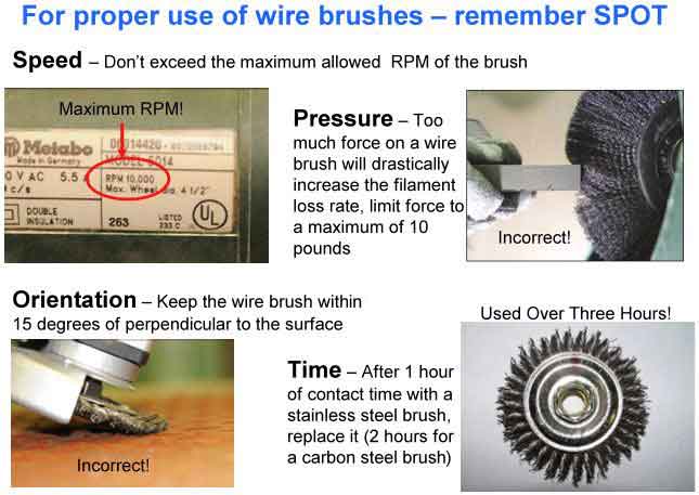
Figure 1. Four key factors that will limit the potential for filament breakage when using a wire brush
Applications and Usage Matrix for Wire Brush Alternatives
Good nuclear plant foreign material exclusion practices minimize the use of wire brushes. Consequently, for workers and supervisors to better implement this practice, an applications and usage matrix for wire brush alternatives was developed. This matrix identifies typical applications (or activities) where wire brushes might be used and suggests alternative products that can be used as a substitution for a wire brush.
This task uses and expands on information contained in the EPRI report Nuclear Maintenance Applications Center: Assessment of Replacement Wire Brushes and will be issued as a wall poster under product number 1022292, Wire Brush and Alternatives Selection Matrix, by the end of this year. This wall poster (see Figure 2) can be displayed in shop and work areas so that workers have a quick and available resource to select alternatives to wire brushes.
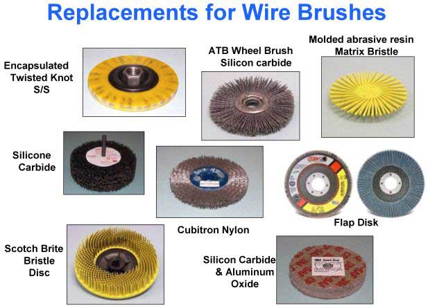
Figure 2. A sample of products available that can be used in lieu of a wire brush
For more information on these EPRI products, contact Nick Camilli, 704.595.2594, ncamilli@epri.com, or Lee Rogers, 772.288.4369, lrogers@epri.com.
EPRI Revising Condition-Based Maintenance Reports
Since the 1980s, EPRI has published various reports relating to predictive or condition-based maintenance programs and technologies. These reports served as a foundation for predictive maintenance within our industry. Many of these reports published are now more than 10 years old. As a result, EPRI is reviewing many of its predictive and condition-based maintenance reports to compare and contrast these reports with current practices, programs, and technologies. The goal is to identify gaps, areas in need of revision, and areas where more focused effort and clarity would prove beneficial. The effort will result in consolidated and updated guidance.
Drafts of this revised guidance will be developed by EPRI personnel in conjunction with consultants and utility personnel and subsequently reviewed by a technical advisory group (TAG) made up of interested utility personnel. Project updates and information on this effort will be sent to predictive/condition-based program managers, predictive maintenance technology experts, and other interested individuals who are on the project's distribution list.
A conference call is scheduled for January 19, 2011, to discuss this effort. Additional periodic conference calls will be scheduled at this time to discuss the project's direction and status. Drafts of the resultant revised guidance will be available during the 2011 Condition-Based Maintenance meetings scheduled for July 11–15, 2011, in Albuquerque, New Mexico. Publication of the results is expected in December 2011.
For information on this effort or to be added to a list of interested utility personnel, contact Jim Sharkey, 704.595.2557, jsharkey@epri.com.
EPRI Publishes Generator Maintenance Guide for EDGs
EPRI is publishing Generator Maintenance Guide for Emergency Diesel Generators (1021479). The report provides guidance on generator maintenance and maintenance programs.
Although generators have been highly reliable during the past 40 years, some plants have identified issues through inspection and testing that demonstrate that more detailed maintenance of these generators should be considered. In addition, with plants moving to life extension, some sites are investigating what maintenance should be done to ensure a high degree of reliability throughout an extended 60-year plant life.
The report was written for persons responsible for the maintenance and maintenance planning for these generators. The intent is for these individuals to review the report along with their maintenance history, operating history, and maintenance program to determine whether their program is adequate to ensure the required level of reliability.
Prior to performing generator maintenance, plant personnel should consider the risks involved in the maintenance being performed and the potential that adverse conditions or significant degradation may be identified. Plants should address contingency planning, the potential use of spares, and the availability and capability of generator expertise and repair shops. Periodic boroscopic inspections can be a valuable inspection tool for identifying degradation in inaccessible areas of the stator and rotor. Boroscopic inspections can be performed with other routine inspection activities, as part of the preventive maintenance program.
The report provides a list of challenges regarding emergency diesel generators (EDG) generator maintenance; a summary of industry operating experience; results of EPRI surveys; a table of generator degradation modes and mechanisms; generator maintenance tasks, strategies, and techniques; a discussion on long-term storage; a discussion on refurbishment/replacement; practical maintenance recommendations; and a list of known generators and their models.
It was proposed that work on EDG generators continue by summarizing the key results of several generator inspections in a way that would provide a useful benchmark or information that could provide justification for maintenance decisions. Key inspection results might include generator make and model; dates of manufacture and installation; operational, environmental, and maintenance history; inspection results summary; any refurbishment or repairs made; and root causes of any degradation found.
For additional information, contact Jim Sharkey, 704.595.2557, jsharkey@epri.com.
Comprehensive Reactor Coolant Pumps and Reactor Recirculation Pumps
Review and Consolidation (1022315 and 1022328)
Over the years, EPRI has published numerous reports relating to reactor coolant pumps (RCPs) and reactor recirculation pumps (RRPs). NMAC conducted a comprehensive review of these reports to ensure that report recommendations were consistent with current practices and each other. The membership can benefit by using the information contained within the affected reports to update their maintenance practices and procedures.
RCP/RCP maintenance is important to sustained generation, and it has a significant impact on outage duration if the latest best practices are not incorporated in work orders used during the refuel outage. If inconsistent information is referenced and used during work order activity development, the resulting work may not be based on the best available information.
The comprehensive RCP/RRP review/consolidation project did the following:
- Identified affected RCP/RRP reports
- Compared and contrasted technical information contained within the reports
- Solicited RCP/RRP subject matter experts (original equipment manufacturers and utility membership)
- Removed report inconsistencies and consolidated redundant information in the reports (revised and reduced number of reports from two to one)
- Updated reports when and where it was beneficial to the membership
- Retired six reports that are no longer a relevant concern to the industry
- Identified those EPRI reports that contain information judged to be beneficial (new or keep)
Table 1 documents the RCP/RRP report changes so that the membership may easily identify reports, internal to their organization, that may need to be revised to reflect the latest best practices.
Table 1. Changes in RCP and RRP reports
| EPRI Report Number | Description | Sub-Component Focus | Action |
|---|---|---|---|
| 1022315 | Westinghouse Reactor Coolant Pump Seal Maintenance Guide | Westinghouse seals | New; Available November 2010 |
| 1000050 | Westinghouse Reactor Coolant Pump Seal Performance Improvement Guide: Supplement To EPRI Main Coolant Pump Seal Maintenance Guide estinghouse Seal Performance Improvement Guide | Westinghouse seals | Consolidated into 1022315 |
| 1007551 | Reactor Coolant Pump RCP Seal High Leakoff Mitigation | Westinghouse seals | Consolidated into 1022315 |
| 1022328 | RCP Seal Maintenance Guide for Non-Westinghouse Seals | Non-Westinghouse seals | New; Available Jan 2011 |
| TR-100855 | Main Coolant Pump Seal Maintenance Guide | Non-Westinghouse seals | Update into 1022328 |
| NP-2611-V1 | Main Coolant Pump Shaft Seal Reliability Investigation, Volume 1 MCP Shaft Seal Reliability | Seal | Retire |
| NP-2965-V1 | Main Coolant Pump Shaft Seal Guidelines, Volume 1: Maintenance Manual GuidelinesMCP Shaft Seal Guide – Volume 1 | Seal | Retire |
| NP-2965-V2 | Main Coolant Pump Shaft Seal Guidelines, Volume 2: Operational GuidelinesMCP Shaft Seal Guide – Volume 2 | Seal | Retire |
| TR-100299 | Proceedings: Main Coolant pump Pump Workshop— Proceedings - 1991 | Various sub-components | Retire |
| TR-102938-V1 | Development of a Main Coolant Pump Seal Decision Support System: Volume 1 MCP Seal Decision Support System | Seal | Retire |
| TR-100154-T1 | Evaluation of Main Coolant Pump Shaft Cracking | Shaft | Retire |
| 1016681 | Nuclear Maintenance Applications Center: Reactor Recirculation Pump Seal Maintenance Guide RRP Seal Maintenance Guide | Boiling water reactor seals | Keep |
| TR-100154-T2 | Evaluation of Main Coolant Pump MCP Shaft Cracking | Shaft | Keep |
| TR-108480 | Considerations for Vibration Monitoring and Diagnostics of the Reactor Coolant Pump | Vibration | Keep |
| NP-6337 | Vibration Monitoring of Main Coolant PumpsCPs | Vibration | Keep |
| 1007895 | Ultrasonic Inspection of Main CoolantMCP Shafts | Manual shaft inspection | Keep |
| 1009660 | Ultrasonic Inspection of Main Coolant MCP Shafts | Automated shaft inspection | Keep |
| 10134561015165 | Nuclear Maintenance Applications Center: Reactor Coolant Pump/Reactor Recirculation Pump Motor Lubrication Oil Systems Maintenance GuideRCP/RRP Motor Lubrication Oil Systems Maintenance Guide | Motor | Keep |
| 1015165 | Diagnostics for Rotating Equipment—RCP Shaft Fatigue Crack Growth RCP Shaft Fatigue Crack Growth Experiments | Shaft crack experiments | Keep |
The project identified and summarized all NMAC reports pertaining to RCP/RRP maintenance. A technical advisory group (TAG) consisting of noted pump experts from the industry was used for validating the technical assertions within the interim draft and final reports. The final reports will be available for membership use in November 2010 (1022315) and January 2011 (1022328).
If you have questions regarding the Westinghouse RCP Seal Maintenance Guide or RCP Seal Maintenance Guide with Non-Westinghouse Seals, contact Tom Turek, 484.631.5863, tturek@epri.com.
Control Rod Drive Hydraulic System Maintenance Guide
The report Control Rod Drive Hydraulic System Maintenance (1021061) identified the best practices and characteristic weaknesses in the control rod drive (CRD) hydraulic system and provided a cost-effective approach to maintaining the system to achieve the highest standard of equipment availability and reliability. The report will be available in March 2011; the primary end users for this report will be maintenance and engineering staff.
It is essential that the maintenance and operational decisions that influence the long-term performance of the CRD hydraulic system be clearly understood and managed in the most cost-effective manner. It is expected that the membership will use the information contained within the subject report to compare CRD maintenance strategies and identify improvement areas that will allow their CRD system to achieve the highest standard of equipment availability and reliability over the entire plant life cycle.
The major components of the CRD system (see Figure 1) consist of the following:
- CRD pumps/gearbox/motors
- Hydraulic control units
- CRD mechanism maintenance strategies
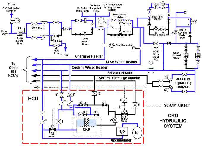
Figure 1. A CRD hydraulic system
For more information about this report, contact Tom Turek, 484.631.5863, tturek@epri.com.
Operator Rounds for Equipment Reliability
AP-913 calls for using several sources of data to support condition monitoring. Operator rounds is one potential source. However, operator rounds is a traditional activity that may not be optimally focused to deliver high impact on equipment reliability. For example, operator rounds can involve duplication of effort with other preventive maintenance (PM) or surveillance tasks, or the data collected may be underused with respect to identifying potential reductions in workload for station personnel. Figure 1 shows an equipment reliability process flowchart.
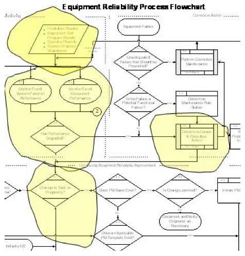
Figure 1. A detail from an equipment reliability flowchart showing the influence of operator rounds on the equipment reliability process
The project effort to date has been focused on the potential for duplication of effort between operator rounds and other PM tasks. Initial results from this in-house review of the Preventive Maintenance Basis Database indicate that there is substantial potential. Needed now is validation of the extent to which this duplication exists at member utilities.
Several low-impact site visits are planned to follow the data collected by operators on rounds from the point of collection to the point of use in condition monitoring. Interplant practices will be compared to identify the extent to which the data collected by operators is useful to the personnel responsible for monitoring the condition of the equipment for the purpose of optimizing the PM program or preventing incipient failure.
The focus of these visits will be to gather information regarding actual use of operator rounds data in equipment condition assessment by others (for example, engineers or maintenance personnel accountable for optimizing overall PM strategies). The use of operator rounds data will be compared with PM interval determination and other condition-assessment tasks to identify best practices for operators to document conditions effectively and to identify best practices for engineers to use operator rounds data to improve efficiency of the PM program.
Now is the time for operations, engineering, and maintenance personnel to join EPRI's technical advisory group and to volunteer to host a site visit. The target audience includes operations, engineering, or maintenance personnel responsible for equipment reliability process ownership and/or performance monitoring, and personnel responsible for predictive or condition-based maintenance process ownership. The benefits of this project are expected to be reduced workload and more effective operational focus on equipment reliability fundamentals.
To participate and gain the benchmarking and site visit benefits, contact David Ziebell, 404.316.9823, dziebell@epri.com.
The Impact of Maintenance Workload on Equipment Reliability
Four site visits are complete in the first year of this multiyear project. The long-term goal of this study is to focus resources on high-value tasks by reducing the number and extent of low value tasks. Early results indicate that achievable reductions in work load—for AP-913 critical and noncritical systems—are found in all of the following areas: surveillance activities; corrective, elective, and other maintenance; preventive maintenance (PM) program; and the processes that drive each one (see Figure 2—credit to technical advisory group [TAG] member James Mertink of South Texas Project for the idea).
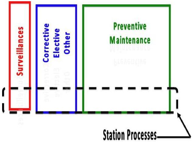
Figure 2: Sources of work affecting equipment reliability
Weeklong visits at Plant Vogtle, South Texas Project, Clinton, and Palo Verde provided the opportunity to objectively identify and quantify low-value tasks (as opposed to quantifying which tasks don't get done because of insufficient resources) and to measure potential effect on resources of low-value tasks.
Now that data collection is complete, EPRI NMAC and the TAG will review the information to identify possible methods (or gaps in use of existing methods) to eliminate or reduce low-value tasks.
Results to date include several instances of "low-hanging fruit," or easily achievable task reductions, including the following:
- Semiannual public address system testing: 1500 hours per year saved by reviewing requirements more carefully even though the system is critical.
- Radwaste storage tank charcoal filter changeout: Use condition monitoring to determine changeout frequency.
- Scaffolding: Up to 9000 hours per year can be outsourced from mechanical maintenance shop. These savings arise in both critical and noncritical work.
- Non-Appendix R emergency lights: Several hundred hours per year are savable if Non-Appendix R lights are tested on a reduced frequency, instead of treating them the same as Appendix R emergency lights simply because the fixtures are the same make and model. There may be additional savings with fixture change-outs to modern design. These savings arise in both critical and noncritical applications.
Additional insights also evident include the following:
- Alignment on the notion of a living PM program among the work groups and among senior management is often not as robust as needed.
- Good results are associated with senior management support; separate and defined processes for PM optimization (PMO) versus living PM program; and establishing numerical targets. (One station is exceeding its goal of >2000 hours per year net reduction in work year after year even though PMO continues to add PM tasks.)
- T-week stability is a key foundation for finding opportunities to reduce work.
- Some PM feedback tools are better than others.
Results to date and project details will be presented in the report Impact of Maintenance Workload on Equipment Reliability: Describing and Quantifying Low-Impact Work (1022243) in December 2010.
Save the Date
On January 19 and 20, 2010, the TAG will meet in Charlotte, North Carolina, to continue this project, including development of methods and pilot applications to find and eliminate low-value work. Your member involvement at this stage in the project will provide valuable benchmarking and may result in your site benefiting from an early pilot application.
For more information, contact David Ziebell, 404.316.9823, dziebell@epri.com, or Lee Catalfomo, 813.996.3357, lcatalfo@epri.com.
NMAC Meetings
2010 EPRI Hoisting, Rigging, and Crane Users Group Annual Meeting
The Hoisting, Rigging, and Crane Users Group (HRCUG) had a busy and productive 2010. This year's annual meeting (see Figure 1) was held in Shreveport, Louisiana. It was feared that the current economy would hurt attendance, but this was not the case. The meeting agenda featured a number of informative presentations and workshops. Presentation topics included single-point failure proof requirements, proper rigging techniques, Significant Operating Experience Report 06-01, and interpreting Occupational Safety and Health Administration regulations relative to the operation of forklift trucks. Separate round table discussions were held on current rigging and lifting issues, as well as materials-handling considerations.
Figure 1. The 2010 HRCUG Meeting in Shreveport, Louisiana
This year's meeting also provided the opportunity to attend two informative workshops. The first workshop was presented by Dan Klasel of Whiting Services on proper crane operation and maintenance practices. The second workshop consisted of a factory tour of Crosby's Lebus manufacturing facilities in Longview, Texas, as shown in Figure 2.
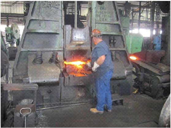
Figure 2. Forging operations at Crosby's Lebus manufacturing facilities in Longview, Texas
In addition to a fascinating look at the forging process that takes billet steel blanks and shapes them into various hooks, shackles, and links, Crosby provided an outstanding catered Texas barbecue lunch, complete with all of the fixings (see Figure 3).
Figure 3. A Texas barbecue lunch at Crosby's Lebus facilities
Arrangements are underway for the 2011 HRCUG meeting. Tentative plans will site the meeting in Chicago, Illinois, near the famous Magnificent Mile. Whiting Corporation has generously offered to host a site visit and tour of its crane manufacturing facilities in Monee, Illinois.
As always, in addition to high-value workshops, the 2011 HRCUG meeting agenda will be filled with pertinent presentations, round table discussions, regulatory updates, and a review of the past year's Institute of Nuclear Power Operations operating experience reports.
For more information, contact Merrill Quintrell, 704.595.2530, mquintrell@hotmail.com.
Rod Control Reliability Committee Working to Improve System Reliability
Rod Control Reliability Committee members continuing reliability improvements to the rod control system
Evaluating Improvements in Rod Control Reliability
Although implementing the maintenance recommendations contained in the EPRI report Nuclear Maintenance Applications Center: Westinghouse Full-Length Rod Control System—Life Cycle Management Planning Sourcebook (1011881) has improved the industry's overall rod control system performance, additional analysis of system reliability events since the report's publication in 2006 should be performed to determine whether revised or additional system maintenance recommendations are warranted. Figure 1 shows the components of a rod control system.
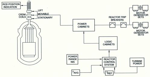
Figure 1. A rod control system
Section 7 of EPRI report 1011881 contains the following:
- 14 recommended reliability improvements
- 22 recommended preventive maintenance and predictive maintenance activities
- 16 good maintenance and design practices
Events that have challenged rod control system reliability since the recommendations provided in EPRI report 1011881 should be analyzed to determine whether the recommendations provided need to be revised or eliminated and whether new recommendations need to be developed.
It is expected that the above project will begin in 2011, pending final budget approvals.
Save the Date
The next Rod Control Reliability Committee (RCRC) meeting will be held June 20–24, 2011, at the Clearwater Florida Sheraton. The regular RCRC meeting will be followed by a workshop on a specified technical topic. The topic for the workshop is currently under discussion.
Registration for this meeting will be issued by the end of the year.
For more information about the RCRC, contact EPRI project manager Lee Rogers, 772.288.4369, lrogers@epri.com; RCRC chairperson Richard Schreiner, 757.365.2552, richard.c.schreiner@dom.com; or RCRC Vice Chairperson Joe Constant, 803.701.5132, joe.constant@duke-energy.com.
Work Planning Managers/Supervisors Working to Improve Work Package Quality
Idaho National Labs (INL) hosted the Work Planning Users Group (WPUG) summer meeting July 13–15, 2010, in Idaho Falls, Idaho. The meeting was well attended by 40 planning professionals.
A portion of the meeting was reserved so that each attendee could express his or her site's work planning challenges and accomplishments. This forum allows for the identification of common issues for the group to focus on, as well as good practices that can be shared among utilities.
Common challenges facing work planning organization include the following:
- Organizational demand for work package content has steadily been increasing.
- The work force is changing with an increasing ratio of first-time supplemental workers.
- Planners don't have a clear target to determine the proper work package content level.
- Work package instructions are being used to close workers knowledge and skill gaps.
- Some corrective action program responses require unnecessary or additional work package barriers or redundancies to be added to work package instructions.
All of the previously stated challenges are impacting the quality of the work package.
Work Package Quality—Top Priority
One of the biggest challenges to work package quality is the alignment of craft training and skills to work package detail or content. This alignment is difficult to attain even in normal circumstances, but with today's changing work force and high ratio of first-time supplemental workers, there seems to be a trend to include more worker knowledge and expectations into the standard work package. Figure 1 shows the gap between work package content and craft skill.
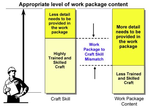
Figure 1. Identifying the gap between work package content and craft skill
Potential Solution to Improve Work Package Quality
WPUG members are considering the development and validation of a process that defines skill of the craft for plant and supplemental workers so that planners can develop work packages that closely match the expected craft skill levels.
Next WPUG Meeting
The next WPUG meeting will be hosted by the Florida Power & Light (FPL)—Turkey Point Nuclear Plant. It will be held January 18–20, 2011, at the FPL General Office Building, 9250 Flagler Street, Miami, Florida. Registration is currently open for this meeting and can be accessed through www.epri.com.
Contact Lee Rogers if you are interesting in participating in the development of the process to define skill of the craft. If you would like to find out more about the WPUG upcoming meeting or activities, contact EPRI project manager Lee Rogers, 772.288.4369, lrogers@epri.com, or WPUG Chairperson John Hodgkinson (San Onofre Nuclear Generating Station), John.Hodgkinson@sce.com, or WPUG Vice Chairperson Steve Johnson (INL), StephenC.Johnson@inl.gov.
Circuit Breaker Users Group Update
This year, the Circuit Breaker Users Group published an Issues Brief that described the group and outlined the issues on which we were working. The EPRI product number is 1021243, and this Issues Brief can be found at www.epri.com.
A series of electrical bus and cable-related failures within the industry has prompted a review of the industry guidance provided on bus maintenance practices. In 2010, EPRI initiated an effort to review electrical bus and cable maintenance practices. Objectives include the following:
- Determining whether the current accepted bus maintenance practices are sufficient for the world's existing fleet of nuclear plants, assuming long-term operation in excess of 40 years
- Determining whether there are alternative maintenance strategies or additional/improved maintenance tasks that could be pursued by the industry
- Identifying and evaluating the value of various technologies used for bus monitoring
This year, the group also reviewed and updated the EPRI Preventive Maintenance Basis Database components relating to medium- and low-voltage switchgear. In addition, progress was made this year on updating and revising the ABB K-Line routine preventive maintenance guidance.
During the users group meeting, working group meetings were held on bus maintenance, motor control center maintenance, circuit breaker specialist training, and the ABB K-Line and HK preventive maintenance.
In 2011, EPRI and the Circuit Breaker Users Group expect to publish revised guidance relating to electrical bus and cable maintenance as well as guidance on the training of circuit breaker specialists and circuit breaker maintenance program owners.
In addition to these efforts, the group will continue to pursue development of guidance on motor control center maintenance.
All materials from the meetings, including results of the surveys, are posted on the following:
- The Circuit Breaker Users Group EPRI collaboration web site
- The meeting web site (under the "EPRI Events" tab)
- The Circuit Breaker Users Group web site on www.epri.com
The target week for the 2011 Circuit Breaker Users Group meeting is the week of June 13, 2011. The location is to be determined. When identified, the meeting dates and location will be confirmed by e-mail to all of the industry's circuit breaker plant primary contacts.
For more information about the Circuit Breaker Users Group, contact Jim Sharkey, 704.595.2557, jsharkey@epri.com.
Mark Your Calendars for Upcoming Joint Emergency Diesel Generator Owners Group Meetings in 2012
In summer 2012, EPRI will present the Joint Emergency Diesel Generator Owners Group Conference. The event will be coordinated with individual emergency diesel generator (EDG) owners group meetings to be held in the June–July 2012 timeframe. This event is co-sponsored by the U.S.-based EDG owners groups, including ALCO, Cooper-Bessemer, Cooper Enterprise (TDI), ESI-EMD, Fairbanks Morse, and the Diesel Fuel Oil Group. The objective of the joint EDG conference is to provide a forum for personnel who operate and maintain EDGs to share information, operational and maintenance experiences, problems and solutions, and techniques to improve EDG reliability and availability.
Individuals wishing to present a paper or deliver a presentation should contact Jim Sharkey, 704.595.2557, jsharkey@epri.com.
Japanese Reliability Centered Maintenance–Condition-Based Maintenance Users Group Update
As a result of regulatory changes, Japanese nuclear utilities are collectively moving toward condition-based maintenance programs. To assist in this effort, EPRI has sponsored the Japanese Reliability Centered-Maintenance–Condition-Based Maintenance (RCM–CBM) Users Group.
The RCM–CBM group is similar to the U.S.-based Condition-Based Maintenance Users Group in that it spends a significant amount of its meeting agenda reviewing plant case histories to expand its knowledge base and highlight lessons learned. The RCM–CBM users group has formed working groups that will meet separately throughout the year to discuss specific technologies including vibration analysis, oil analysis, and infrared thermography.
This year, the group surveyed all members and developed a prioritized list of topics to be addressed and resolved. These topics include the following:
- Extending the scope of condition-based maintenance (CBM)
- Establishing and modify acceptance criteria
- Collecting and learning from case histories and CBM diagnosis examples
- Expanding and clarifying what type of equipment and which condition-monitoring techniques can be effectively applied
- CBM engineer education, training, and qualifications
- Best practices for obtaining management support
- Introduction of techniques other than vibration, infrared thermography, and oil analysis
- Databases for managing the results of condition monitoring and evaluation
EPRI is working to assist the group in addressing issues pertaining to acceptance criteria and expanding and clarifying what type of equipment and which condition-monitoring techniques can be effectively applied.
This year, a white paper was developed by a U.S. utility to address some questions relating to the establishment and modification of acceptance criteria. The paper describes an approach taken by one plant to systematically conduct machine vibration analysis. The paper provides suggestions for establishing action thresholds, describes a systematic response if action thresholds are exceeded, and suggests the use of documents and information to aid the analyst in evaluating vibration conditions.
For 2011, the group will continue discussing and addressing the issues listed previously. General group meetings will be held in May and October. Working groups will convene, but dates and locations are yet to be determined.
Selected technology experts from U.S. and international utilities attend these meetings to provide an international exchange and share their programs, experience, methods, and case histories. In conjunction with these meetings, benchmarking trips to Japanese nuclear plant sites are attended by predictive maintenance program and technology experts from other countries.
Utility personnel interested in sharing successful programs or unique case studies should contact Jim Sharkey, 704.595.2557, jsharkey@epri.com. For information or questions regarding this group and these EPRI initiatives, contact Jim Sharkey.
Combined Condition-Based Maintenance Meeting
The Combined CBM meeting is an annual event held during the second full week in July
Mark Your Calendars
The 2011 combined Condition-Based Maintenance (CBM) meeting will be held at the Hyatt Regency in Albuquerque, New Mexico, July 11–15, 2011.
Background
The Combined CBM meeting is actually the union of four separate groups that share a common interest: safely improving equipment reliability in the most cost-effective manner.
The four separate groups are the following:
- Predictive Maintenance Users Group (PdMUG)
- Vibration Technology Forum (VTF)
- Infrared Thermography Users Group (IRUG)
- Lubrication and Bearing
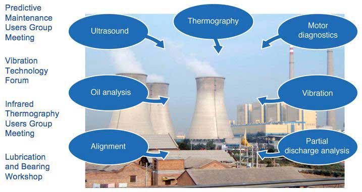
The objectives of these groups are to identify issues and common challenges related to safety, cost control, and equipment reliability. Equally important, the group members also represent a vast body of knowledge that EPRI collectively draws from to formulate solutions and communicate those solutions to the membership, which benefits the entire industry. Although the PdMUG focuses on the programmatic issues that are challenging our industry, each technology venue (vibration, infrared [IR] thermography, and lube oil) focuses specifically on data collection, analysis, and equipment problem resolution.
The meeting provides a forum for EPRI members to exchange information, ideas, successes, problems, and experiences regarding diagnostic monitoring and condition-assessment technologies used in condition-based maintenance programs.
Robert Waterman of the NASA JFK Space Center was the 2010 keynote speaker. Bob presented the program Fault Detection, Isolation, and Recovery for NASA's Exploration Technology Development Program. Most of us in the audience related well with the challenges that both NASA and the utility industry face: capturing knowledge and integrating information to improve equipment reliability in the safest, most cost-effective manner.
The groups accomplish the meeting objectives by EPRI updates, case studies, round table sessions, and workshops.
EPRI Updates
EPRI staff presents updates to the membership on the status of upcoming products and initiatives that would best benefit the membership.
In July 2010, EPRI provided the following updates for the membership:
- Automation of troubleshooting/diagnostics of power plant equipment faults
- Plant view data integration
- IR thermography (IRT) severity criteria project
- Using a preventive maintenance basis to build a CBM program
- EPRI lubrication updates and resources
Case Studies
Case studies are essentially plant experience reports that are presented and/or discussed by utility personnel. Case studies typically discuss current or past equipment problems; completed, planned, or potential corrective actions; cost benefit information; and any other pertinent information that would assist attendees. The application of new technologies and innovations is also highlighted during each of these meetings.
If you were unable to make the meeting this year and still would like to download any of the 50-plus presentations, all meeting material for 2010 (including workshops) and historic meeting material from 2006 to the present is available at www.epri.com. Look in the EPRI "Collaboration" tab, with a project name of "Condition-Based Maintenance (CBM)," and then look under the "Documents" tab. If you have any difficulty, just give any one of us a call. We are here to serve the membership.
Round Table Sessions
Round table sessions provide an opportunity for the membership to identify programmatic or technical issues while other members offer beneficial insight on the pros and cons of paths taken to resolve those issues. If a resolution to an issue is not available and there is sufficient common interest, EPRI will evaluate the merit of developing a member-sanctioned initiative to provide a solution.
The following round table topics were discussed in July 2010:
- Pumps: foundations, lubrication, performance, and thermodynamic pump parameters
- CBM program metrics
- IRT certification
- Lubrication: programs, new/replacement options, sample port installations, and oil testing
- Large turbine instrumentation and monitoring
- Operational deflection shapes
- Nuclear in-service testing
Workshops
Workshops address those issues that most affect equipment reliability and challenge safe generation. The EPRI staff studies utility operating experience, issues and reviews membership surveys, and identifies industry trends that may be potentially problematic for the membership. Subject matter experts present informed solutions to resolve the issues or at least minimize the membership's exposure to generation or financial risk.
In July 2010, EPRI hosted the following workshop topics presented by industry-recognized technical leaders:
- Proper lubrication of rolling element bearings (SKF)
- Torsional monitoring (Structural Integrity)
- Iso-Phase bus duct monitoring (EPRI)
- Lubrication and Bearing workshop with numerous workshop topics including the following:
- Turbine oil management
- Filter media
- Grease sampling and testing
2010 Proposals and Accomplishments
The Predictive Maintenance Users group elected to form a subcommittee to develop more meaningful CBM performance indicators that would address the CBM program performance issues, such as bench strength adequacy.
The VTF identified the need for monitoring components that are inaccessible at power, such as containment fans. To that end, the VTF proposed that EPRI pursue a project to correlate motor casing vibration data with motor control center (MCC) motor torque spectra of (motor) bearing frequencies. The benefit to the membership is that now you will have actionable criteria to apply to the MCC torque spectra where none existed previously.
The IRUG continues to make progress on the IRT severity criteria software project (1018639) due in 2011. The Lubrication and Bearing Workshop members are responsible for the release of the report Nuclear Maintenance Applications Center: Effective Greasing Practices (1020247) in 2010.
For information on each of the specific groups, contact the following EPRI staff:
- PdMUG or VTF: Tom Turek, 484.631.5863, tturek@epri.com
- IRUG: Gary Noce, 484.432.9251, gnoce@epri.com
- Lubrication and Bearings: Nick Camilli, 704.595.2594, ncamilli@epri.com
If you would like to know more or are interested in participating in the IRT severity criteria software project, contact Gary Noce, 484.432.9251, gnoce@epri.com.
Large Electric Motor Users Group Holds August 2010 Meeting
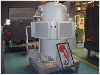
Used with permission from TVA
The August 2010 Large Electric Motor Users Group (LEMUG) meeting took place in Pittsburgh, Pennsylvania, and included two joint motor and pump sessions. One of the joint sessions included workshops that covered topics related to pump and motor, such as lubricants, rotor dynamics, and alignment. The workshop sessions ran concurrently, and attendees chose from any of the three topics. Tours of the Westinghouse and Curtiss-Wright Facilities were conducted in conjunction with the workshops and joint sessions. The joint motor and pump users group session was held on Tuesday, August 17, and covered topics on remote inspections, motor and pump gear systems, bearing oil level issues, and operating history of wet-wound boiler circulation pumps.
The LEMUG had presentations on technical topics, such as magnetic forces in electric motors, case study using on-line monitoring, partial discharge in electric motors, and issues related to bearing failures. Several program-related topics, such as equipment reliability and AP-913, the procurement and installation of critical spares from other than the original equipment manufacturer, material substitution for qualified motors, and resin treatment issues, were covered. Presentations on topics related to technology improvements for maintaining or operating electric motors were part of the LEMUG meeting. The two technology improvement presentations provided at this meeting related to load testing of electric motors using dynamometers. Having the capability to full load test an electric motor provides a good tool for design confirmation as well as for electric motor maintenance.
LEMUG working groups have developed guidance for purchase and repair specifications, guidance on motor troubleshooting, and recommendations on managing the maintenance of electric motors, such as tiered motor maintenance and repair versus replacement.
The LEMUG has three working groups within its organizational structure. They are as follows:
- Application
- Information
- Maintenance
The aim for these working groups is to provide an opportunity for more focused activities in areas that will improve the reliability, availability, and performance of electric motors in power plant applications. These goals are accomplished by users brainstorming on topics in certain areas that often lead to the development of industry guides.
At the August 2010 meeting, the working groups continued with their efforts to develop guidance on the development of an electric motor specialist, properly collecting electric motor failure data, discussing the development of a comprehensive motor guide, reviewing capability of commercial core testers, guidance for a low-voltage motor specification, additional symptom charts for motor troubleshooting, and auxiliary devices used for electric motors.
The next LEMUG meeting is scheduled for January 24–27, 2011, in Phoenix, Arizona.
Check the EPRI Events calendar at EPRI.com or contact Wayne Johnson, 704.595.2551, wejohnson@epri.com, for more details on the upcoming meeting.
Transformer Protection—Focus of 2010 Transformer and Switchyard Users Group Meeting
The purpose of the Transformer and Switchyard Users Group (TSUG) is to aid nuclear power plant personnel in their efforts to maintain reliable transformers and switchyard equipment.
The TSUG meeting was held July 26–28, 2010, at the Mansion on Forsyth in Savannah, Georgia. Savannah was selected because of its proximity to a new transformer manufacturing facility built by EFACEC (a Portuguese manufacturer of electrical equipment). The plant has plans to supply large shell-form transformer units to the United States and world markets.
The meeting provided the opportunity for power plant personnel to hear from leading experts in the field of transformer testing and monitoring, as well as gather lessons learned from other power plant personnel.
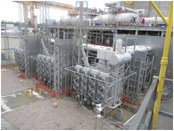
Figure 1. A new GSU transformer installation at a Progress Energy plant
Used with permission from Progress Energy
The meeting was fortunate to have Dr. Michel Duval, one of the leading experts in dissolved gas in oil analysis, present on changes being considered in the interpreting and monitoring of dissolved gas in oil values for large power transformers. The developer of the Duval triangle has continued to work on methods to better understand the behavior of dissolved gas in oil and to make recommendation on transformer conditions based on these analyses.
Dr. Poorvi Patel of ABB presented on advanced testing for larger power transformers. Her presentation covered much of the work being done by ABB in its Transformer Remanufacturing and Engineering Services group. Dr. Patel discussed the group's efforts related to managing mature transformers, design reviews, high-voltage testing, and advanced diagnostics, such as digital frequency response analysis.
Another informative presentation was made by Shawn Simon of the Institute of Nuclear Power Operations to update the industry on its findings from reviewing transformer failures and site assessments. Presentations from industry personnel such as Kevin Beatty (Progress Energy), John Amoo-Otoo (Exelon), Shannon McArdle (NEIL), and others made for an informative meeting.
The TSUG is uniquely organized to address industry issues. The current organization of the users group consists of an administrative structure and three working groups. Several changes were made in the organizational structure of the TSUG with the selection of a new group secretary and two new working group chairs. Longtime group secretary Thomas Manning retired from his job at Seabrook, and Jeff McClelland of DC Cook Station stepped down as switchyard equipment working group chair. TSUG has the following organizational structure:
- Group chair: Kirk Robbins, Exelon
- Group co-chair: Camilo Rodriguez, First Energy
- Secretary: Christy Adams, Duke Energy
- Working groups:
- Power transformers: Nick Pournaras, Southern Nuclear
- Switchyard equipment: Cameron Lee, Duke Energy
- Grid reliability: Bill Duge, First Energy
On Thursday following the actual TSUG meeting, members of the transformer working group and others remained for a Copper Book review session. There were two sections or chapters reviewed for completion in 2010: Chapter 7, Operations, and Chapter 8, Monitoring and Diagnostics.
The Copper Book is the name given to the Transformer Resource Book that is being developed by EPRI. The Copper Book is a cross-sector effort within EPRI to collect all the knowledge related to transformers used in utility applications and place that information in one resource. The sectors involved are power delivery, nuclear, and generation. It is the goal of this effort to provide a single reference for those who will be specifying, operating, monitoring, and maintaining transformers. In order to ensure that the effort will be a useful resource to the industry, it is imperative to have input from the equipment users—these review sessions provide just that opportunity.
For more information regarding the TSUG meeting and/or the Copper Book review session, contact Wayne Johnson, 704.595.2551, wejohnson@epri.com.
Transformer and Switchyard Users Group Power Transformer Protection Workshop
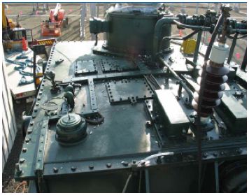
Used with permission from Hydro-Quebec
Large power transformers are equipped with various devices and schemes that protect a transformer from thermal, electromagnetic, electrodynamics, and transient occurrences. Some issues that can affect a transformer are partial discharge, gassing, faults (internal and external), switching transients, inrush, overexcitation, and temperature.
In recent years, several conventional large oil-filled power transformer failures have been reported. Some transformers have been exposed to overvoltage and other events that stress transformer insulation.
The goal was to provide a 4 hour workshop to utility system, component, and maintenance engineers; equipment specialists; and technicians who covered protection for typical power plant transformers (especially generator step-ups, auxiliaries, and startup) and the typical devices used to protect and/or monitor transformers. One objective was to provide information that users could implement for better monitoring and asset management decisions. Another major objective was to assist the user in reducing forced outages and transformer failures.
The workshop material covered classic devices used to protect a transformer while in operation, such as overcurrent and ground fault protection (including arresters); application of differential protection to transformers; restricted ground fault protection; gas relays (pressure and gas accumulation); winding temperature; and oil temperature devices.
The workshop presented transformer protection from a systematic perspective. The workshop discussed the devices used to protect the transformer core, the windings and insulation, the thermal devices, and the mechanical devices used to deal with tank pressure and liquid level. In this short workshop, the goal was to introduce the particular devices while reinforcing the reason for their application for the protection of power transformers.
A later presentation was provided during the users group meeting that focused on the types of protective relaying used for large power transformers. Protective relaying is an artful science, and the combination of the philosophy of transformer protection and the devices used to accomplish that task provides a substantial overview of transformer protection.
If you have any questions regarding this material, contact Wayne Johnson, 704.595.2551, wejohnson@epri.com.
Emerson Hosts Diagnostic Workshop at Japanese Valve Users Group Meeting
The second annual Japanese Valve Users Group meeting was held October 20–21, 2010, in Tokyo, Japan. Approximately 60 Japanese utility members attended, representing nine utilities. The theme for this year's meeting was air-operated valve (AOV) diagnostics. Understanding the valve condition prior to maintenance can go a long way in ensuring that appropriate maintenance tasks are completed as needed, thereby strengthening the overall preventive maintenance (PM) program while maximizing plant resources. Additionally, diagnostics allow for performance trending and set-point verification to ensure optimum performance from the control valve assembly.
Day one of the users group meeting began with a workshop on valve diagnostics presented by Ron Hager of Emerson Process Management (Fisher Division), as shown in Figure 1. A morning presentation provided background information on AOV diagnostics, including description of tests, basic valve setup, test methods, control valve basics, and control valve optimization. The afternoon session was fully devoted to live demonstrations with mockup valve assemblies. Fisher demonstrated an air leak and excessive packing friction on a direct acting actuator and a faulty positioner on a rotary valve. In each case, dynamic scans were discussed with the audience and the traces were analyzed.
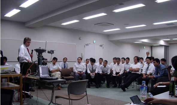
Figure 1. Ron Hager (Emerson) demonstrates a diagnostic setup and tests on a direct acting actuator
Day two of the meeting included case histories from each Japanese utility. Topics ranged from development or application of valve diagnostics to an improved inspection method of vacuum containment breakers. Bill Bowyer from Southern Nuclear Operating Company (SNC) presented an overview of SNC's AOV program. Additionally, he presented multiple case histories that emphasize the importance and use of diagnostics in SNC's AOV program. The day concluded with updates of EPRI NMAC valve projects by Nick Camilli and a technical discussion of safety relief valve alternative testing fluids and aging springs presented by Bob O'Neill. Figure 2 shows Makoto Kurebayashi of Japan Atomic Power Company presenting on the development of an AOV diagnostic system.
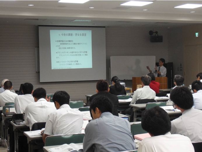
Figure 2: Makoto Kurebayashi of Japan Atomic Power Company gives a presentation on the development of an AOV diagnostic system
Details of next year's meeting will be forthcoming.
For more information about the Japanese Valve Users Group meeting, contact Nick Camilli, 704.595.2594, ncamilli@epri.com.
Pump Users Group Meeting
The NMAC Pump Users Group (PUG) meeting in 2010 was held in beautiful downtown Pittsburgh, Pennsylvania, August 16–20, 2010 (see Figures 1 and 2). Pittsburgh was the unanimous choice by the PUG for the opportunity to tour Westinghouse in Waltz Mill and to tour Curtiss-Wright EMD in Cheswick. As it turned out, the NMAC Large Electric Motor Users Group (LEMUG) also chose Pittsburgh for its 2010 meeting. This became one of those rare meetings where mechanical and electrical engineers coexisted for nearly a full week.
The meeting had a strong focus on training, with Monday dedicated to three separate workshop sessions in separate tracks of the following:
- Rotor dynamics and bearing design
- Lubrication
- Intermediate vibrations
- Tours by both groups to Westinghouse Waltz Mill facilities
In the afternoon, two of the three tracks were repeated and the LEMUG members had the opportunity to also visit Westinghouse Waltz Mill.
Tuesday morning was a joint session of the PUG and the LEMUG, covering presentations of interest to both groups. In the afternoon, all had the opportunity to tour the Curtiss-Wright EMD facilities, where we had excellent presentations at all steps in the building and testing of the AP1000 canned reactor coolant pump.
EPRI hosted a joint PUG and LEMUG vendors fair and reception Wednesday evening, and the vendors hosted a special event Tuesday evening.
The Tuesday-through-Thursday portion of the PUG meeting covered several key issues, including the following:
- Remote inspection in high-radiation areas
- Equipment aging and obsolescence issues
- New metalizing technology work done at Public Service Electric & Gas Co.
- Laser welding process shaft repairs
- Main feedwater pump high bearing temperature
- Testing of one new reactor coolant pump seal at Surry plant
- Advanced diamond coating R&D by EagleBurgmann
- Charging pump failure analysis
- Broken coupling, gearbox, and pump distress
- Effects of ultrapure water on mechanical seals
- NMAC's new comprehensive pump guide resource
- Recent OE/key hotline questions handled by the PUG e-mail group
All of these presentations were provided to attendees at the end of the meeting and are available to download by logging in to www.epri.com, selecting "Users Websites," scrolling down to "Nuclear and Pump Users Group (PUG)," and selecting the "Meeting and Minutes" button on the left.
The PUG members voted in the business session to plan a meeting in conjunction with Sulzer Corporation in Portland, Oregon, for the second week of August in 2011. Also considered were potential meeting locations in Charlotte, North Carolina; Chattanooga, Tennessee; and Chicago, Illinois. Only members—no vendors—were allowed to vote. More information will be posted on the EPRI NMAC PUG web site and in e-mails to all of our PUG members.
Nearly 50% of the attendees stayed over to Friday morning to begin working on guides. Tim Buyer of Dominion North Anna is the working group chair. He is leading the effort on revising the Feedwater Maintenance Guide (1018699). Jim Tipton from NextEraEnergy Seabrook Plant is leading the effort to develop a strategic pump program under his Aging and Obsolescence Working Group. It is expected that these reports will be worked on through 2011 into 2012. Draft versions of both will be circulated to the technical advisory group and posted on the PUG collaborative web site as they become available.
Annually, the PUG will provide a deliverable report containing the following key parts:
- PUG meeting presentations and training provided
- Updates as needed for the maintenance guides under development and being revised
- Selected hotline questions of high importance submitted to the PUG and all responses
- Look-ahead plans for the upcoming meetings
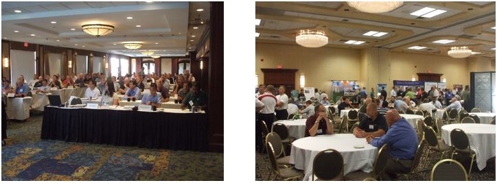
| Figure 1. PUG meeting session | Figure 2. PUG vendor fair and discussions |
For professional development credits for the training, contact Alessandra Ozorio, 704.595.2620, aozorio@epri.com. For more information about the meeting, contact Alessandra Ozorio or Dave Dobbins, 704.595.2560, ddobbins@epri.com, or go directly to www.epri.com and search events in Nuclear in August 2011. You do not need an EPRI ID or password to register for this meeting.
Terry Turbine Users Group Meeting
For 2010, the 18th Terry Turbine Users Group (TTUG) meeting was held in the Denver, Colorado, area in cooperation with Woodward Controls at the Embassy Hotel in Centennial, Colorado, July 13–15. The Boiling Water Reactors Owners Group also met in the same hotel. The TTUG meeting focused on sharing timely information from suppliers for Terry Turbine equipment and plant operating experience (OE). The attendance is just another indication that despite its low operating hours, Terry Turbine controls equipment is very important plant safety equipment and is having many end-of-useful-life issues. Dresser-Rand presented an update on its new replacement digital governor and installations going on presently and planned for the balance of 2010 and into 2011.
For 2010, the focus areas included the following:
- Auxiliary feedwater/reactor core isolation coolant/high pressure coolant injection breakout session
- Discussion about a request from Callaway about adding OE into the maintenance guides
- Selected hotline questions, including the following:
- Boroscopic inspection versus full tear-down on 6- to 12-year basis
- Steam admission valve leakage
- Mechanical overspeed issues
- Trip and throttle valve leakage across seat
- Auxiliary feedwater pump high outboard bearing temperature at Prairie Island
- Digital controls replacement round table, including the following:
- Support on aging controls
- Dresser-Rand review status of installations
- San Onofre Nuclear Generating Station installation and results
- Farley installation and results
- Clinton plans for reactor core isolation cooling
- Advanced controls demonstration by ESI of the new Woodward 505 (see Figures 1 and 2)
- Trip and throttle valve issues at 9 Mile Point
- Developing your plant goals for Institute of Nuclear Power Operations upper-quartile discussion session
- Training tour of NMAC and TTUG web sites
- Expanded pooled inventory management for TTUG
All of these presentations were provided to attendees at the end of the meeting and are available to download by logging in to www.epri.com, selecting "Users Websites," scrolling down to "Nuclear" and "Terry Turbine Users Group (TTUG)," and selecting the "Meeting and Minutes" button on the left.
For 2011, the TTUG meeting will be held in the Orlando, Florida area as usual in the second week of July. The exact dates and format and whether there will be a workshop have not been determined. There will be as a minimum a two-plus day TTUG meeting (verify by visiting Terry Turbine Users Group meeting information in "July 2011 Events" for any changes). If you are interested in presenting a paper on your plant issues, contact Dave Dobbins.
A hands-on tentatively planned workshop session will be followed by a two-day meeting on key issues and technical challenges. The workshop typically includes hands-on refresher training sessions of 4 hours, each covering turbine disassembly and reassembly, trip and throttle valves, overspeed trip, electric and hydraulic governors, and, for 2011, an added training session on the Woodward 505 controls. The workshops and meetings have been well attended over the years, and the reviews for the hands-on training have been very good because everyone wants to learn from the masters and not under the outage pressures at their plant.
Annually, the TTUG will provide a deliverable report containing the following key parts:
- TTUG meeting presentations and training provided
- Updates as needed for the TTUG maintenance guides especially as the controls are replaced with the new digital system design(s) and/or OE is added to the maintenance guides
- Selected hotline questions submitted to the TTUG of high importance and all responses
- Look-ahead plans for the upcoming meetings
The TTUG will continue to employ an outside expert to consult on generic issues for the overall TTUG, not for the benefit of one plant.
Multimedia Training Modules for 2011
During the 2010 four-day intensive Terry Turbine training, NMAC hired a professional cameraman to record most of the training sessions. These recordings could lead to a major change in the training approach for the TTUG. The training would continue to support the needs of the TTUG as the skill level shifts and as the training needs may be shifted to an outside company, and multimedia Terry Turbine training modules would be developed for our members with greater emphasis on computers and video and less on manuals. A sample of the training class was digitally recorded by a professional cameraman, and a sample video is on www.youtube.com—search NMAC TTUG, and click on it (the sample video runs eight minutes).
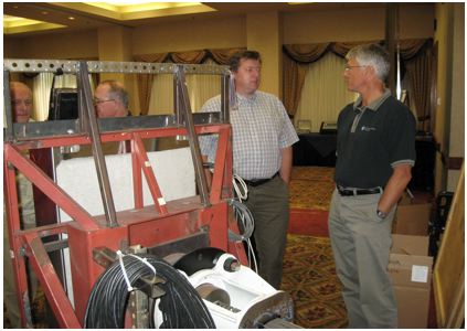
Figure 1. The Woodward 505 panel opened
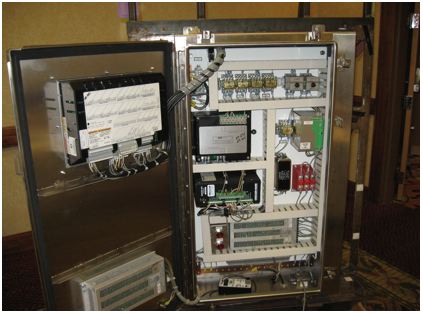
Figure 2. The mockup used for the training class on the last day by ESI
Anyone interested in being on the technical advisory group for these training modules should contact Dave Dobbins, 704.595.2560, ddobbins@epri.com. For more information on the TTUG, contact Dave Dobbins, or go to www.epri.com webpage and search events in Nuclear in July 2011. You do not need an EPRI ID or password to register for this meeting.
Mark Your Calendars for Upcoming Joint Emergency Diesel Generator Owners Group Meetings in 2012
In the summer of 2012, EPRI will present the Joint Emergency Diesel Generator Owners Group Conference. The event will be coordinated with individual emergency diesel generator (EDG) owners group meetings to be held in the June–July 2012 time-frame. This event is co-sponsored by the U.S.-based EDG owners groups including ALCO, Cooper-Bessemer, Cooper Enterprise (TDI), ESI-EMD, Fairbanks Morse, and the Diesel Fuel Oil Group. The objective of the joint EDG conference is to provide a forum for personnel who operate and maintain EDGs to share information, operational and maintenance experiences, problems and solutions, and techniques to improve EDG reliability and availability.
Individuals wishing to present a paper or presentation should contact Jim Sharkey, 704.595.2557, jsharkey@epri.com.
Pressure Relief Device Interest Group Update and Status
This year's annual Pressure Relief Device Interest Group (PRDIG) meeting was held last January in Orlando, Florida, and we are looking forward to next year's meeting, which will be January 17–19, also in Orlando.
Although many technical meetings had experienced a drop-off in attendance, we were pleased with the number of attendees and the mix of domestic and international plant representatives.
This year's presentations addressed several issues, including the elements of a successful pressure relief valve (PRV) in-house test and repair facility from three different plants, repair and setting of PRVs, sticking metal seats, reduction of labor and/or exposure when removing and re-installing main steam safety valves, and an update of ASME Operations and Maintenance Code changes. Although the upcoming meeting's agenda has not been finalized, the following topics and issues have been identified for presentations and discussions:
- The update to Safety and Relief Valve Testing and Maintenance Guide (TR-105872) will be discussed to solicit group input and request and seek experienced individuals to participate in the technical advisory group (TAG).
- Qualifications of contractors to assist in outages will be considered.
- A summary of the safety relief valve (SRV)–PRV program at Electricité de France plants will be given.
- Issues related to the aging of SRVs and PRVs will be discussed (Are there any revisions to maintenance procedures and parts replacement?).
- Discussions of related operating experience will be held as prompted by the group.
- EPRI assistance to plants since the last group meeting will be discussed.
- The last topic, "In with the new and out with the old," sounds great on every New Year's Day, but how does this relate to the many plant engineers and maintenance personnel as the young come in and the gray hairs leave? This affects the areas of passing on and retaining experience, training, mentoring, and so forth.
For more information, contact Bob O'Neill, 508.539.3301, roneill@epri.com.
2011 NMAC Meetings
| Users Groups | ||||
| Meeting | 2011 Date | Location | Contact | Phone |
| MOV–PPM Users Group | January 2011 | TBD | John Hosler | 704.595.2720 |
| Pressure Relief Device Interest Group | January 17–19, 2011 | Orlando, FL | Bob O'Neil | 508.539.3301 |
| Work Planning Users Group | January 18–20, 2011 | Miami, FL | Lee Rogers | 772.288.4369 |
| Large Electric Motor Users Group/Workshop | January 24–27, 2011 | Phoenix, AZ | Wayne Johnson | 704.595.2551 |
| Maintenance Rule Users Group/Workshop | February 8–10, 2011 | Garden Grove, CA | Marty Bridges | 704.595.2672 |
| Japanese RCM–CBM Users Group | May 17–19, 2011 | Sendai, Japan | Jim Sharkey | 704.595.2557 |
| Rod Control System Users Group | June 20–24, 2011 | Clearwater, FL | Lee Rogers | 772.288.4369 |
| Hoisting, Rigging, and Crane Users Group | June 21–23, 2011 | Chicago | Merrill Quintrell | 704.595.2530 |
| Combined Condition-Based Maintenance (PdMUG/IRUG/VTF/Lubrication and Bearing) | July 11–15, 2011 | Albuquerque, NM | Tom Turek | 484.631.5863 |
| Terry Turbine Users Group | July 13–14, 2011 | Orlando, FL | Dave Dobbins | 704.595.2560 |
| Work Planning Users Group | July 2011 | TBD | Lee Rogers | 772.288.4369 |
| Transformer and Switchyard Users Group | July 2011 | TBD | Wayne Johnson | 704.595.2551 |
| Preventive Maintenance Basis Database Users Group | August 8–12, 2011 | Charlotte, NC | Jim McKee | 256.437.9296 |
| Maintenance Rule Users Group | August 2011 | TBD | Marty Bridges | 704.595.2672 |
| Circuit Breaker Users Group | June 13–17, 2011 | TBD | Jim Sharkey | 704.595.2557 |
| Pump Users Group/Workshop | August 8–11, 2011 | Portland, OR | Dave Dobbins | 704.595.2560 |
| Large Electric Motor Users Group | August 2011 | TBD | Wayne Johnson | 704.595.2551 |
| Japanese RCM–CBM Users Group | October 26–28, 2011 | Tokyo, Japan | Jim Sharkey | 704.595.2557 |
| Japanese Valve Users Group | October 2011 | Japan | Nick Camilli Bob O'Neil | 704.595.2594 508.539.3301 |
| Workshops | ||||
| Meeting | 2011 Date | Location | Contact | Phone |
| Large Electric Motor Workshop | January 24, 2011 | Phoenix, AZ | Wayne Johnson | 704.595.2551 |
| Maintenance Rule Workshop | February 8, 2011 | Garden Grove, CA | Marty Bridges | 704.595.2672 |
| Rod Control Workshop | June 2011 | TBD | Lee Rogers | 772.288.4369 |
| Whiting Crane Workshop and Factory Tour | June 21, 2011 | Monee, IL | Merrill Quintrell | 704.595.2530 |
| MOV–PPM Training | July 2011 | TBD | John Hosler | 704.595.2720 |
| Terry Turbine User Group Workshop | TBD | Orlando, FL | Dave Dobbins | 704.595.2560 |
| Transformer and Switchyard Workshop | July 2011 | TBD | Wayne Johnson | 704.595.2551 |
| Pump Workshop/Users Group | August 2011 | Portland, OR | Dave Dobbins | 704.595.2560 |
| Large Electric Motor Workshop/Users Group | August 2011 | TBD | Wayne Johnson | 704.595.2551 |
| Steering Committee Meetings | ||||
| Meeting | 2011 Date | Location | Contact | Phone |
| NMAC Integration Committee Meeting | February 15–16, 2011 | Charlotte, NC | Marty Bridges | 704.595.2672 |
| NMAC Integration Committee Meeting | September 2011 | Charlotte, NC | Marty Bridges | 704.595.2672 |
| NMAC Japanese Technical Advisory Committee Meeting | October 2011 | Japan | Marty Bridges | 704.595.2672 |
| NMAC European Technical Advisory Committee Meeting | TBD | TBD | Marty Bridges | 704.595.2672 |
NMAC Domestic Membership
- AmerenUE
- American Electric Power
- Arizona Public Service
- Constellation
- Detroit Edison
- Dominion Energy
- Duke Energy
- Energy Northwest
- Entergy
- Exelon
- First Energy
- Florida Power & Light
- INL (NA)
- Knolls Atomic Power Labs (KAPL)
- Luminant
- Nebraska Public Power
- NNSA Oak Ridge (ORNL)
- Omaha Public Power
- Pacific Gas & Electric
- PPL Susquehanna
- Progress Energy
- Public Service Electric & Gas
- South Carolina E&G
- South Texas Operating Co.
- Southern California Edison
- Southern Nuclear Operating Co.
- Tennessee Valley Authority
- Wolf Creek
- Xcel Energy Services
NMAC International Membership
- Almaraz (Spain)
- Asco (Spain)
- British Energy (UK)
- Bruce Power (Canada)
- Cernavoda (Romania)
- CFE (Mexico)
- Chubu (Japan)
- Chugoku (Japan)
- Cofrentes (Spain)
- CEZ (Czech Republic)
- Daya Bay (China)
- Electrabel (Belgium)
- Electricité de France
- Electronuclear (Brazil)
- Eskom (South Africa)
- Hokkaido (Japan)
- Hokuriku (Japan)
- Hydro Quebec
- JAPCO (Japan)
- J-Power (Japan)
- Kansai (Japan)
- KHNP (Korea)
- KRSKO (Slovenia)
- Kyushu (Japan)
- Leibstadt (Switzerland)
- NASA (Argentina)
- New Brunswick
- Ontario Power (Canada)
- Santa Maria De Garona (Spain)
- Shikoku (Japan)
- Slovenske Electrarne (Slovakia)
- Taiwan Power
- TEPCO (Japan)
- Tohoku (Japan)
- Trillo (Spain)
- Vandellos (Spain)
NMAC Personnel
| Name | Title | Phone | Coverage Area | |
| Marty Bridges | Program Manager, NMAC | 704.595.2672 | mbridges@epri.com | Maintenance, Engineering, Operations |
| Gary Boles | Consulting Employee | 707-595-2781 | gboles@epri.com | Mechanical Component, Component Engineering, Maintenance Processes, Work Planning |
| Nicholas Camilli | Sr. Project Engineer/Scientist | 704.595.2594 | ncamilli@epri.com | Lubrication, Mechanical Support, Valves and Bolting, Power Uprates |
| Lee Catalfomo | Sr. Project Manager | 813.996.3357 | lcatalfo@epri.com | Equipment Reliability, Maintenance Process Improvement, Operations Support |
| Dave Dobbins | Sr. Project Manager | 704.595.2560 | ddobbins@epri.com | Pumps, Terry Turbines |
| Alan Grunsky | Sr. Program Manager, NSTI | 704.595.2556 | agrunsky@epri.com | Nuclear Steam Turbine Initiative |
| Wayne Johnson | Sr. Project Manager | 704.595.2551 | wejohnson@epri.com | Electrical Components, Electrical Systems, Motors |
| Jim McKee | Sr. Project Manager | 704-595-2777 | jmckee@epri.com | Electrical / I&C, Predictive Maintenance (PdM), Maintenance Program Development and Optimization, System Engineering |
| Bob O'Neill | Consulting Employee | 508.539.3301 | roneill@epri.com | MOVs, SOVs, PRVs, AOVs |
| Alessandra Ozorio | Technical Assistant I | 704.595.2620 | aozorio@epri.com | Administration & Coordination, International Interface |
| Merrill Quintrell | Sr. Project Manager | 704.595.2530 | mquintrell@epri.com | Hoists, Rigging, and Cranes |
| Mike Pugh | Consulting Employee | 919.812.5162 | mpugh@epri.com | Condensers, Circulating Water Systems, Mechanical Components, Lubrication |
| Lee Rogers | Sr. Project Manager | 772.288.4369 | lrogers@epri.com | Maintenance Processes, Work Planning, Foreign Material Exclusion, Power Uprates |
| Deborah Rouse | Administrative Assistant | 704.595.2520 | drouse@epri.com | Program Administration |
| Jim Sharkey | Sr. Project Manager | 704.595.2557 | jsharkey@epri.com | Circuit Breakers, Main Generators, Emergency Diesel Generators |
| Tom Turek | Sr. Project Manager | 484.631.5863 | tturek@epri.com | CBM with a Focus on Rotating Equipment |
| David Ziebell | Sr. Project Manager | 404.316.9823 | dziebell@epri.com | Operations & Maintenance (O&M) Processes and Practices, Clearance and Tagging, Change Management |